 |
Electronic Components Datasheet Search |
|
|
Electronic Components Datasheet Search |
|
The question interval is too short.
Please try again in a few seconds.

Hello, Please ask a question about PI3DPX1202A2 Datasheet
# Example questions:
➢ What are the inputs and outputs related to the aux channel?
➢ Explain how each method achieves the reset function.
➢ What is the recommended minimum duration the enable pin must be de-asserted before being re-asserted for proper reset?
| Part No. | PI3DPX1202A2 |
| Manufacturer | DIODES |
| Size | 3Mb |
| Pages | 51 pages |
| Description | Low power DisplayPort 1.2 Redriver with DDC/AUX CH Switch |





This is a good start to a datasheet or technical document for the PI3DPX1202A. Here's a breakdown of what you're doing well and suggestions for improvement, along with potential next steps for expanding the documentation. I've also organized the response to make it easier to digest.
Overall Assessment:
️· Good Start: You're hitting the key elements: block diagram, functional description, power-up timing, and reset implementation. The effort to explain the reset implementation with both external capacitor and GPO control is excellent.
️· Technical Correctness: The content *seems* technically sound based on the limited information provided, but a full assessment would require deeper domain expertise.
️· Formatting & Readability: The columnar formatting is a bit clunky. Paragraphs are very short. This needs refinement for better flow. Diagram references (e.g., "Figure 4-2") should be consistent in style.
️· Missing Information: This is a *very* preliminary datasheet. It lacks crucial details (see "Next Steps" below).
️· Target Audience: The level of detail suggests this is aimed at engineers.
Detailed Feedback & Suggestions:
1. Figure References and Numbering:
️· Consistency: Ensure all figures are sequentially numbered and that references in the text *exactly* match the figure number.
️· Captioning: Each figure should have a clear and concise caption describing its purpose.
2. Text Formatting & Style:
️· Paragraph Length: Combine short paragraphs to create more flowing explanations. Break up longer explanations with headings and bullet points.
️· Language: Use precise and technical language. Avoid colloquialisms.
️· Terminology: Define any specialized terminology when it's first used.
3. Power-Up Timing (Figure 4-2):
️· Specify Time Values: Replace "10mS" with a more formal designation like "≤ 10ms" (less than or equal to 10 milliseconds). Include tolerances (e.g., "≤ 10ms ± 100ns").
️· Specify Signals: Clearly label the axes of the diagram (e.g., Time vs. Voltage, Time vs. Signal Level).
️· Threshold Voltages: Mention the voltage levels considered to be "stable" or "minimum recommended operation voltage" for the power supply.
️· Transition Times: Specify the transition times for the ENABLE signal.
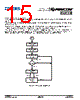
4. Reset Implementation (Figure 4-4):
️· Capacitor Value Selection: Provide guidance on calculating the optimal capacitor value, including formulas or tables. Account for factors such as input voltage slope, impedance, and load.
️· GPO Control Details: Elaborate on how the GPO (General Purpose Output) can be used for reset control.
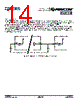
5. Block Diagram (Figure 4-1):
️· Pin Labels: Provide a detailed mapping of the block diagram components to the physical pins of the chip.
️· Signal Flow: Use arrows to clearly show the direction of signal flow.
️· Legend: Include a legend to explain the symbols used in the block diagram.
Next Steps - Expanding the Documentation:
This is where you build out a robust datasheet. Here's a prioritized list:
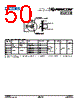
1. Electrical Characteristics Table: *This is critical.* This table will specify the key electrical parameters of the device (supply voltage range, input high/low voltage thresholds, output drive strength, timing parameters, etc.).
2. Pin Descriptions: A detailed description of each pin, including its function, input/output type, and default state.
3. Functional Description (Expanded):
- EQ Selection: Explain the function of the EQ pin and how to use it.
- Voltage Swing Control: Describe the voltage swing control functionality.
- Pre-Emphasis Control: Explain how pre-emphasis is applied and why it's important.
- I2C Programming: Detail the I2C programming interface, including addresses, register map, and command sequences.
- Cable Adapter Detection (CAD): Elaborate on the CAD mechanism.
- Hot Plug Detection (HPD): Detail the HPD function.
4. Operating Modes: Clearly define all operating modes of the device (e.g., normal mode, power-down mode, I2C programming mode).
This is a good start to a datasheet or technical document for the PI3DPX1202A. Here's a breakdown of what you're doing well and suggestions for improvement, along with potential next steps for expanding the documentation. I've also organized the response to make it easier to digest.
Overall Assessment:
️· Good Start: You're hitting the key elements: block diagram, functional description, power-up timing, and reset implementation. The effort to explain the reset implementation with both external capacitor and GPO control is excellent.
️· Technical Correctness: The content *seems* technically sound based on the limited information provided, but a full assessment would require deeper domain expertise.
️· Formatting & Readability: The columnar formatting is a bit clunky. Paragraphs are very short. This needs refinement for better flow. Diagram references (e.g., "Figure 4-2") should be consistent in style.
️· Missing Information: This is a *very* preliminary datasheet. It lacks crucial details (see "Next Steps" below).
️· Target Audience: The level of detail suggests this is aimed at engineers.
Detailed Feedback & Suggestions:
1. Figure References and Numbering:
️· Consistency: Ensure all figures are sequentially numbered and that references in the text *exactly* match the figure number.
️· Captioning: Each figure should have a clear and concise caption describing its purpose.
2. Text Formatting & Style:
️· Paragraph Length: Combine short paragraphs to create more flowing explanations. Break up longer explanations with headings and bullet points.
️· Language: Use precise and technical language. Avoid colloquialisms.
️· Terminology: Define any specialized terminology when it's first used.
3. Power-Up Timing (Figure 4-2):
️· Specify Time Values: Replace "10mS" with a more formal designation like "≤ 10ms" (less than or equal to 10 milliseconds). Include tolerances (e.g., "≤ 10ms ± 100ns").
️· Specify Signals: Clearly label the axes of the diagram (e.g., Time vs. Voltage, Time vs. Signal Level).
️· Threshold Voltages: Mention the voltage levels considered to be "stable" or "minimum recommended operation voltage" for the power supply.
️· Transition Times: Specify the transition times for the ENABLE signal.
4. Reset Implementation (Figure 4-4):
️· Capacitor Value Selection: Provide guidance on calculating the optimal capacitor value, including formulas or tables. Account for factors such as input voltage slope, impedance, and load.
️· GPO Control Details: Elaborate on how the GPO (General Purpose Output) can be used for reset control.
5. Block Diagram (Figure 4-1):
️· Pin Labels: Provide a detailed mapping of the block diagram components to the physical pins of the chip.
️· Signal Flow: Use arrows to clearly show the direction of signal flow.
️· Legend: Include a legend to explain the symbols used in the block diagram.
Next Steps - Expanding the Documentation:
This is where you build out a robust datasheet. Here's a prioritized list:
1. Electrical Characteristics Table: *This is critical.* This table will specify the key electrical parameters of the device (supply voltage range, input high/low voltage thresholds, output drive strength, timing parameters, etc.).
2. Pin Descriptions: A detailed description of each pin, including its function, input/output type, and default state.
3. Functional Description (Expanded):
- EQ Selection: Explain the function of the EQ pin and how to use it.
- Voltage Swing Control: Describe the voltage swing control functionality.
- Pre-Emphasis Control: Explain how pre-emphasis is applied and why it's important.
- I2C Programming: Detail the I2C programming interface, including addresses, register map, and command sequences.
- Cable Adapter Detection (CAD): Elaborate on the CAD mechanism.
- Hot Plug Detection (HPD): Detail the HPD function.
4. Operating Modes: Clearly define all operating modes of the device (e.g., normal mode, power-down mode, I2C programming mode).
| Part No. | PI3DPX1202A2 |
| Manufacturer | DIODES |
| Size | 3Mb |
| Pages | 51 pages |
| Description | Low power DisplayPort 1.2 Redriver with DDC/AUX CH Switch |
| Does ALLDATASHEET help your business so far? [ DONATE ] |
About Alldatasheet | Advertisement | Contact us | Privacy Policy | Link to Datasheet | Link Exchange | Manufacturer List All Rights Reserved©Alldatasheet.com |
| Russian : Alldatasheetru.com | Korean : Alldatasheet.co.kr | Spanish : Alldatasheet.es | French : Alldatasheet.fr | Italian : Alldatasheetit.com Portuguese : Alldatasheetpt.com | Polish : Alldatasheet.pl | Vietnamese : Alldatasheet.vn Indian : Alldatasheet.in | Mexican : Alldatasheet.com.mx | British : Alldatasheet.co.uk | New Zealand : Alldatasheet.co.nz |
|
Family Site : ic2ic.com |
icmetro.com |
 English ▼
  Chinese
 German
 Japanese
 Russian
 Korean
 Spanish
 French
 Italian
 Portuguese
 Polish
 Vietnamese
 Indian
 Mexican
 British
 New Zealand