|
Electronic Components Datasheet Search |
|
|
Electronic Components Datasheet Search |
|
RI-RFM-006A Datasheet(PDF) 19 Page - Texas Instruments |
|
|
|||||||||||||||||||||||||||||
RI-RFM-006A Datasheet(HTML) 19 Page - Texas Instruments |
|
|
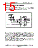
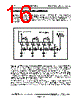
19 / 20 page  Rev. 3.5 RI-RFM-006A TIRIS RF-Module IC for Automotive Page 18 of 19 Wiring for Antenna Circuit As previously described, the FSK signals sent from a remote TIRIS transponder are normally found within a band of 120 kHz to 140 kHz. Therefore, the signal receiving circuit of this TIRIS Transmitter- Receiver System is designed so that the signal amplification factor is necessarily highest within this band. Because of this, all signals and noises which are produced by other devices and whose frequencies fall within this band greatly affect the system performance, especially, its available data communication distance with the remote TIRIS transponder among others. In the same way, they have quite the undesirable effect not only upon the environment in which the proper antenna for the system is found, but also upon the wire used to connect it with the IC’s “A1IN” pin which works as the first-phase amplifier for received signals. Furthermore, if there are wires for square or pulse wave logic signals containing high-frequency components (even though their fundamental frequencies are low) very close to this antenna connection wire, the system’s available data communication distance with the remote TIRIS transponder is further shortened due to the adverse effects of such wires. For all that, if there is no other alternative than to use a long wiring between the IC and its external antenna, it is suggested that a shielded wire be used for antenna wiring in either way as illustrated below. With this, the antenna wiring will be less susceptible to the aforementioned adverse effects. a. When the antenna is driven first. b. When the capacitor is driven first. RI45538NS 7 8 TXLO TXHI To receiver amplifier Shielded wire Antenna Antenna resonance capacitor RI45538NS 78 TXLO TXHI To receiver amplifier Shielded wire Antenna Antenna resonance capacitor |
|
|
Link URL |
| Does ALLDATASHEET help your business so far? [ DONATE ] |
About Alldatasheet | Advertisement | Contact us | Privacy Policy | Link to Datasheet | Link Exchange | Manufacturer List All Rights Reserved©Alldatasheet.com |
| Russian : Alldatasheetru.com | Korean : Alldatasheet.co.kr | Spanish : Alldatasheet.es | French : Alldatasheet.fr | Italian : Alldatasheetit.com Portuguese : Alldatasheetpt.com | Polish : Alldatasheet.pl | Vietnamese : Alldatasheet.vn Indian : Alldatasheet.in | Mexican : Alldatasheet.com.mx | British : Alldatasheet.co.uk | New Zealand : Alldatasheet.co.nz |
|
Family Site : ic2ic.com |
icmetro.com |
 English ▼
 English
 Chinese
 German
 Japanese
 Russian
 Korean
 Spanish
 French
 Italian
 Portuguese
 Polish
 Vietnamese
 Indian
 Mexican
 British
 New Zealand