|
Electronic Components Datasheet Search |
|
|
Electronic Components Datasheet Search |
|
SD8017 Datasheet(PDF) 6 Page - SHOUDING Shouding Semiconductor |
|
|
|||||||||||||||||||||||||||||
SD8017 Datasheet(HTML) 6 Page - SHOUDING Shouding Semiconductor |
|
|
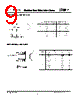
6 / 9 page  The SD8017 constantly monitors the BAT pin voltage programmed value, the SD8017 terminates the the SD8017 enters standby float voltage (4.2V), the SD8017 enters the SD8017 supplies approximately 1/10 the components. Furthermore, the SD8017 is capable final float voltage accuracy of ±1%. The SD8017 The SD8017 is a single cell lithium-ion battery Revision 10/9/2008 current are calculated using the following equations: 1060 1060 , PROG CHG CHG PROG VV RI IR == , The charge current out of the BAT pin can be determined at any time by monitoring the PROG pin voltage using the following equation: 1060 PROG BAT PROG V I R =• This actual current will vary from IC to IC. The typical variation is within +/-20%. Operation charger using a constant-current/constant-voltage algorithm. It can deliver up to 800mA of charge current (using a good thermal PCB layout) with a includes an internal P-channel power MOSFET and thermal regulation circuitry. No blocking diode or external current sense resistor is required; thus, the basic charger circuit requires only two external of operating from a USB power source. Normal Charge Cycle A charge cycle begins when the voltage at the VCC pin rises above the UVLO threshold level and a 1% program resistor is connected from the PROG pin to ground or when a battery is connected to the charger output. If the BAT pin is less than 2.8V, the charger enters trickle charge mode. In this mode, programmed charge current to bring the battery voltage up to a safe level for full current charging. When the BAT pin voltage rises above 2.8V, the charger enters constant-current mode, where the programmed charge current is supplied to the battery. When the BAT pin approaches the final constant-voltage mode and the charge current begins to decrease. When the charge current drops to 1/10 of the programmed value, the charge cycle ends. Programming Charge Current The charge current is programmed using a single resistor from the PROG pin to ground. The battery charge current is 1060 times the current out of the PROG pin. The program resistor and the charge Charge Termination A charge cycle is terminated when the charge current falls to 1/10th the programmed value after the final float voltage is reached. This condition is detected by using an internal, filtered comparator to monitor the PROG pin. When the PROG pin voltage falls below 100mV for longer than tTERM (typically 1ms), charging is terminated. The charge current is latched off and mode, where the input supply current drops to 200mA. (Note: C/10 termination is disabled in trickle charging and thermal limiting modes). When charging, transient loads on the BAT pin can cause the PROG pin to fall below 100mV for short periods of time before the DC charge current has dropped to 1/10th the programmed value. The 1ms filter time (tTERM) on the termination comparator ensures that transient loads of this nature do not result in premature charge cycle termination. Once the average charge current drops below 1/10th the charge cycle and ceases to provide any current through the BAT pin. In this state, all loads on the BAT pin must be supplied by the battery. 6 www.shouding.net SD8017 Shouding |
|
|
Link URL |
| Does ALLDATASHEET help your business so far? [ DONATE ] |
About Alldatasheet | Advertisement | Contact us | Privacy Policy | Link to Datasheet | Link Exchange | Manufacturer List All Rights Reserved©Alldatasheet.com |
| Russian : Alldatasheetru.com | Korean : Alldatasheet.co.kr | Spanish : Alldatasheet.es | French : Alldatasheet.fr | Italian : Alldatasheetit.com Portuguese : Alldatasheetpt.com | Polish : Alldatasheet.pl | Vietnamese : Alldatasheet.vn Indian : Alldatasheet.in | Mexican : Alldatasheet.com.mx | British : Alldatasheet.co.uk | New Zealand : Alldatasheet.co.nz |
|
Family Site : ic2ic.com |
icmetro.com |
 English ▼
 English
 Chinese
 German
 Japanese
 Russian
 Korean
 Spanish
 French
 Italian
 Portuguese
 Polish
 Vietnamese
 Indian
 Mexican
 British
 New Zealand