|
Electronic Components Datasheet Search |
|
|
Electronic Components Datasheet Search |
|
AT89S53 Datasheet(PDF) 18 Page - ATMEL Corporation |
|
|
|||||||||||||||||||||||||||||
AT89S53 Datasheet(HTML) 18 Page - ATMEL Corporation |
|
|
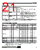
18 / 35 page  AT89S53 0787E–MICRO–3/06 18 Idle Mode In idle mode, the CPU puts itself to sleep while all the on- chip peripherals remain active. The mode is invoked by software. The content of the on-chip RAM and all the spe- cial functions registers remain unchanged during this mode. The idle mode can be terminated by any enabled interrupt or by a hardware reset. Note that when idle mode is terminated by a hardware reset, the device normally resumes program execution from where it left off, up to two machine cycles before the internal reset algorithm takes control. On-chip hardware inhibits access to internal RAM in this event, but access to the port pins is not inhibited. To eliminate the possibility of an unexpected write to a port pin when idle mode is termi- nated by a reset, the instruction following the one that invokes idle mode should not write to a port pin or to exter- nal memory. Power-down Mode In the power-down mode, the oscillator is stopped and the instruction that invokes power-down is the last instruction executed. The on-chip RAM and Special Function Regis- ters retain their values until the power-down mode is terminated. Exit from power-down can be initiated either by a hardware reset or by an enabled external interrupt. Reset redefines the SFRs but does not change the on-chip RAM. The reset should not be activated before V CC is restored to its normal operating level and must be held active long enough to allow the oscillator to restart and stabilize. To exit power-down via an interrupt, the external interrupt must be enabled as level sensitive before entering power- down. The interrupt service routine starts at 16 ms (nomi- nal) after the enabled interrupt pin is activated. Program Memory Lock Bits The AT89S53 has three lock bits that can be left unpro- grammed (U) or can be programmed (P) to obtain the additional features listed in the following table. When lock bit 1 is programmed, the logic level at the EA pin is sampled and latched during reset. If the device is pow- ered up without a reset, the latch initializes to a random value and holds that value until reset is activated. The latched value of EA must agree with the current logic level at that pin in order for the device to function properly. Once programmed, the lock bits can only be unpro- grammed with the Chip Erase operations in either the parallel or serial modes. Notes: 1. U = Unprogrammed 2. P = Programmed Status of External Pins During Idle and Power-down Modes Mode Program Memory ALE PSEN PORT0 PORT1 PORT2 PORT3 Idle Internal 1 1 Data Data Data Data Idle External 1 1 Float Data Address Data Power-down Internal 0 0 Data Data Data Data Power-down External 0 0 Float Data Data Data Lock Bit Protection Modes(1)(2) Program Lock Bits Protection Type LB1 LB2 LB3 1 U U U No internal memory lock feature. 2 P U U MOVC instructions executed from external program memory are disabled from fetching code bytes from internal memory. EA is sampled and latched on reset and further programming of the Flash memory (parallel or serial mode) is disabled. 3 P P U Same as Mode 2, but parallel or serial verify are also disabled. 4 P P P Same as Mode 3, but external execution is also disabled. |
|
Link URL |
| Does ALLDATASHEET help your business so far? [ DONATE ] |
About Alldatasheet | Advertisement | Contact us | Privacy Policy | Link to Datasheet | Link Exchange | Manufacturer List All Rights Reserved©Alldatasheet.com |
| Russian : Alldatasheetru.com | Korean : Alldatasheet.co.kr | Spanish : Alldatasheet.es | French : Alldatasheet.fr | Italian : Alldatasheetit.com Portuguese : Alldatasheetpt.com | Polish : Alldatasheet.pl | Vietnamese : Alldatasheet.vn Indian : Alldatasheet.in | Mexican : Alldatasheet.com.mx | British : Alldatasheet.co.uk | New Zealand : Alldatasheet.co.nz |
|
Family Site : ic2ic.com |
icmetro.com |
 English ▼
 English
 Chinese
 German
 Japanese
 Russian
 Korean
 Spanish
 French
 Italian
 Portuguese
 Polish
 Vietnamese
 Indian
 Mexican
 British
 New Zealand