|
Electronic Components Datasheet Search |
|
|
Electronic Components Datasheet Search |
|
PPC405GPR-3JB400Z Datasheet(PDF) 38 Page - Applied Micro Circuits Corporation |
|
|
|||||||||||||||||||||||||||||
PPC405GPR-3JB400Z Datasheet(HTML) 38 Page - Applied Micro Circuits Corporation |
|
|
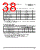
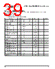
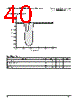
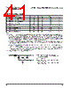
38 / 57 page  405GPr – Power PC 405GPr Embedded Processor 38 AMCC Revision 2.04 – September 7, 2007 Data Sheet Absolute Maximum Ratings The absolute maximum ratings below are stress ratings only. Operation at or beyond these maximum ratings can cause permanent damage to the device Characteristic Symbol Value Unit Supply Voltage (Internal Logic) VDD 0 to +1.95 V Supply Voltage (I/O Interface) OVDD 0 to +3.6 V PLL Supply Voltage AVDD 0 to +1.95 V Input Voltage (1.8V CMOS receivers) VIN -0.6 to VDD + 0.45 V Input Voltage (3.3V LVTTL receivers) VIN -0.6 to OVDD + 0.6 V Input Voltage (5.0V LVTTL receivers) VIN -0.6 to OVDD + 2.4 V Storage Temperature Range TSTG -55 to +150 °C Case temperature under bias TC -40 to +120 °C Notes: 1. All specified voltages are with respect to GND. 2. Empirical data indicates that all chip voltages should begin to ramp-up within 1 ms of each other. There should never be voltage present at the I/O pins before OVDD is within operating range. Package Thermal Specifications The PPC405GPr is designed to operate within a case temperature range of -40°C to +85°C3. Thermal resistance values for the E-PBGA packages (leaded and lead-free) in a convection environment are as follows: Package—Thermal Resistance Symbol Airflow ft/min (m/sec) Unit 0 (0) 100 (0.51) 200 (1.02) 35mm, 456-balls—Junction-to-Case θ JC 222 °C/W 35mm, 456-balls—Case-to-Ambient1 θ CA 14 13 12 °C/W 27mm, 456-balls—Junction-to-Case θ JC 222 °C/W 27mm, 456-balls—Case-to-Ambient1 θ CA 18 16 15 °C/W Notes: 1. For a chip mounted on a JEDEC 2S2P card without a heat sink. 2. For a chip mounted on a card with at least one signal and two power planes, the following relationships exist: a. Case temperature, TC, is measured at top center of case surface with device soldered to circuit board. b. TA = TC – P×θCA, where TA is ambient temperature and P is power consumption. c. TCMax = TJMax – P×θJC, where TJMax is maximum junction temperature and P is power consumption. 3. 333MHz operated at 266MHz or less can operate at +105°C. |
|
Link URL |
| Does ALLDATASHEET help your business so far? [ DONATE ] |
About Alldatasheet | Advertisement | Contact us | Privacy Policy | Link to Datasheet | Link Exchange | Manufacturer List All Rights Reserved©Alldatasheet.com |
| Russian : Alldatasheetru.com | Korean : Alldatasheet.co.kr | Spanish : Alldatasheet.es | French : Alldatasheet.fr | Italian : Alldatasheetit.com Portuguese : Alldatasheetpt.com | Polish : Alldatasheet.pl | Vietnamese : Alldatasheet.vn Indian : Alldatasheet.in | Mexican : Alldatasheet.com.mx | British : Alldatasheet.co.uk | New Zealand : Alldatasheet.co.nz |
|
Family Site : ic2ic.com |
icmetro.com |
 English ▼
 English
 Chinese
 German
 Japanese
 Russian
 Korean
 Spanish
 French
 Italian
 Portuguese
 Polish
 Vietnamese
 Indian
 Mexican
 British
 New Zealand