|
Electronic Components Datasheet Search |
|
|
Electronic Components Datasheet Search |
|
38B7 Datasheet(PDF) 64 Page - Renesas Technology Corp |
|
|
|||||||||||||||||||||||||||||
38B7 Datasheet(HTML) 64 Page - Renesas Technology Corp |
|
|
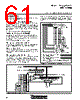
64 / 110 page  38B7 Group SINGLE-CHIP 8-BIT CMOS MICROCOMPUTER MITSUBISHI MICROCOMPUTERS 63 15.75 µs 64 µs 64 µs64 µs64 µs 64 µs m = 0 m = 7 m = 8 m = 9 m = 63 16.0 µs 15.75 µs15.75 µs 15.75 µs15.75 µs15.75 µs Pulse width modulation register H: 00111111 Pulse width modulation register L: 000101 Sub-periods where “H” pulse width is 16.0 µs: m = 8, 24, 32, 40, 56 Sub-periods where “H” pulse width is 15.75 µs: m = all other values 4096 µs Data Setup The PWM output pin also function as port P96. Set port P96 to be the PWM output pin by setting bit 0 of the PWM control register (address 002616) to “1”. The high-order 8 bits of output data are set in the high-order PWM register PWMH (address 003516) and the low-order 6 bits are set in the low-order PWM register PWML (address 003616). PWM Operation The timing of the 14-bit PWM function is shown in Figure 65. The 14-bit PWM data is divided into the low-order 6 bits and the high-order 8 bits in the PWM latch. The high-order 8 bits of data determine how long an “H” level sig- nal is output during each sub-period. There are 64 sub-periods in each period, and each sub-period t is 256 ✕ τ (= 64 µs) long. The signal’s “H” has a length equal to N times τ, and its minimum reso- lution = 250 ns. The last bit of the sub-period becomes the ADD bit which is speci- fied either “H” or “L,” by the contents of PWML. As shown in Table 11, the ADD bit is decided either “H” or “L.” That is, only in the sub-period tm shown in Table 11 in the PWM cycle period T = 64 t, the “H” duration is lengthened during the minimum resolution width τ period in comparison with the other period. For example, if the high-order eight bits of the 14-bit data are “0316” and the low-order six bits are “0516,” the length of the “H” level output in sub-periods t8, t24, t32, t40 and t56 is 4 τ, and its length 3 τ in all other sub-periods. Time at the “H” level of each sub-period almost becomes equal because the time becomes length set in the high-order 8 bits or becomes the value plus t, and this sub-period t (= 64 µs, approxi- mate 15.6 kHz) becomes cycle period approximately. Table 11 Relationship between low-order 6-bit data and setting period of ADD bit 0 0 0 0 0 0 None 0 0 0 0 0 1 m = 32 0 0 0 0 1 0 m = 16, 48 0 0 0 1 0 0 m = 8, 24, 40, 56 0 0 1 0 0 0 m = 4, 12, 20, 28, 36, 44, 52, 60 0 1 0 0 0 0 m = 2, 6, 10, 14, 18, 22, 26, 30, 34, 38, 42, 46, 50, 54, 58, 62 1 0 0 0 0 0 m = 1, 3, 5, 7, .................................................., 57, 59, 61, 63 LSB Sub-periods tm lengthened (m = 0 to 63) Low-order 6-bit data Transfer From Register to Latch Data written to the PWML register is transferred to the PWM latch once in each PWM period (every 4096 µs), and data written to the PWMH register is transferred to the PWM latch once in each sub- period (every 64 µs). Pulses output from the PWM output pin correspond to this latch contents. When the PWML register is read, the contents of the latch are read. However, bit 7 of the PWML register indicates whether the transfer to the PWM latch is completed: the transfer is completed when bit 7 is “0”, it is not done when bit 7 is “1”. Fig. 65 PWM timing |
|
Link URL |
| Does ALLDATASHEET help your business so far? [ DONATE ] |
About Alldatasheet | Advertisement | Contact us | Privacy Policy | Link to Datasheet | Link Exchange | Manufacturer List All Rights Reserved©Alldatasheet.com |
| Russian : Alldatasheetru.com | Korean : Alldatasheet.co.kr | Spanish : Alldatasheet.es | French : Alldatasheet.fr | Italian : Alldatasheetit.com Portuguese : Alldatasheetpt.com | Polish : Alldatasheet.pl | Vietnamese : Alldatasheet.vn Indian : Alldatasheet.in | Mexican : Alldatasheet.com.mx | British : Alldatasheet.co.uk | New Zealand : Alldatasheet.co.nz |
|
Family Site : ic2ic.com |
icmetro.com |
 English ▼
 English
 Chinese
 German
 Japanese
 Russian
 Korean
 Spanish
 French
 Italian
 Portuguese
 Polish
 Vietnamese
 Indian
 Mexican
 British
 New Zealand