|
Electronic Components Datasheet Search |
|
|
Electronic Components Datasheet Search |
|
LTC1419CSW Datasheet(PDF) 12 Page - Linear Technology |
|
|
|||||||||||||||||||||||||||||
LTC1419CSW Datasheet(HTML) 12 Page - Linear Technology |
|
|
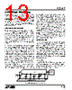
12 / 20 page  12 LTC1419 APPLICATIONS INFORMATION Differential Inputs The LTC1419 has a unique differential sample-and-hold circuit that allows rail-to-rail inputs. The ADC will always convert the difference of + AIN – (–AIN) independent of the common mode voltage (see Figure 11a). The common mode rejection holds up to extremely high frequencies, see Figure 10a. The only requirement is that both inputs can not exceed the AVDD or AVSS power supply voltages. Integral nonlinearity errors (INL) and differential nonlinearity errors (DNL) are independent of the common mode voltage, however, the bipolar zero error (BZE) will vary. The change in BZE is typically less than 0.1% of the common mode voltage. Dynamic performance is also affected by the common mode voltage. THD will degrade as the inputs approach either power supply rail, from 86dB with a common mode of 0V to 76dB with a common mode of 2.5V or – 2.5V. Figure 10b. Selectable 0V to 5V or ±2.5V Input Range Differential inputs allow greater flexibility for accepting different input ranges. Figure 10b shows a circuit that converts a 0V to 5V analog input signal with only an additional buffer that is not in the signal path. Full-Scale and Offset Adjustment Figure 11a shows the ideal input/output characteristics for the LTC1419. The code transitions occur midway between successive integer LSB values (i.e., – FS + 0.5LSB, – FS + 1.5LSB, – FS + 2.5LSB,... FS – 1.5LSB, FS – 0.5LSB). The output is two’s complement binary with 1LSB = FS – (– FS)/16384 = 5V/16384 = 305.2 µV. In applications where absolute accuracy is important, offset and full-scale errors can be adjusted to zero. Offset error must be adjusted before full-scale error. Figure 11b shows the extra components required for full-scale error adjustment. Zero offset is achieved by adjusting the offset ANALOG INPUT 1419 F11b 1 2 3 R4 100 Ω R7 50k R3 24k 5V R6 24k R8 50k R5 47k 4 5 0.1 µF 10 µF +AIN –AIN VREF REFCOMP AGND LTC1419 + Figure 11b. Offset and Full-Scale Adjust Circuit Figure 10a. CMRR vs Input Frequency Figure 11a. LTC1419 Transfer Characteristics 1419 F11a 011...111 011...110 000...001 000...000 111...111 111...110 100...001 100...000 FS – 1LSB – (FS – 1LSB) INPUT VOLTAGE [+AIN – (–AIN)] INPUT FREQUENCY (Hz) 1 80 70 60 50 40 30 20 10 0 10 100 1419 G09 1000 10000 LTC1419 +AIN ANALOG INPUT –AIN VREF 0V TO 5V REFCOMP AGND 1419 F10 1 2 3 ±2.5V 4 5 10 µF – + |
|
|
Link URL |
| Does ALLDATASHEET help your business so far? [ DONATE ] |
About Alldatasheet | Advertisement | Contact us | Privacy Policy | Link to Datasheet | Link Exchange | Manufacturer List All Rights Reserved©Alldatasheet.com |
| Russian : Alldatasheetru.com | Korean : Alldatasheet.co.kr | Spanish : Alldatasheet.es | French : Alldatasheet.fr | Italian : Alldatasheetit.com Portuguese : Alldatasheetpt.com | Polish : Alldatasheet.pl | Vietnamese : Alldatasheet.vn Indian : Alldatasheet.in | Mexican : Alldatasheet.com.mx | British : Alldatasheet.co.uk | New Zealand : Alldatasheet.co.nz |
|
Family Site : ic2ic.com |
icmetro.com |
 English ▼
 English
 Chinese
 German
 Japanese
 Russian
 Korean
 Spanish
 French
 Italian
 Portuguese
 Polish
 Vietnamese
 Indian
 Mexican
 British
 New Zealand