|
Electronic Components Datasheet Search |
|
|
Electronic Components Datasheet Search |
|
HCPL0708 Datasheet(PDF) 8 Page - Agilent(Hewlett-Packard) |
|
|
|||||||||||||||||||||||||||||
HCPL0708 Datasheet(HTML) 8 Page - Agilent(Hewlett-Packard) |
|
|
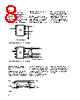
8 / 10 page  8 Application Information Bypassing and PC Board Layout The HCPL-0708 optocoupler is extremely easy to use. No external interface circuitry is required because the HCPL-0708 uses high-speed CMOS IC technology allowing CMOS logic to be connected directly to the inputs and outputs. As shown in Figure 6, the only external component required for proper operation is the bypass capacitor. Capacitor values should be between 0.01 µF and 0.1 µF. For each capacitor, the total lead length between both ends of the capacitor and the power-supply pins should not exceed 20 mm. Figure 7 illustrates the recommended printed circuit board layout for the HPCL-0708. Figure 6. Recommended printed circuit board layout. Figure 7. Recommended printed circuit board layout. Propagation Delay, Pulse-Width Distortion and Propagation Delay Skew Propagation Delay is a figure of merit which describes how quickly a logic signal propagates through a system. The propaga- tion delay from low to high (tPLH) is the amount of time required for an input signal to propagate to the output, causing the output to change from low to high. Similarly, the propagation delay from high to low (tPHL) is the amount of time required for the input signal to propagate to the output, causing the output to change from high to low. See Figure 8. Figure 8. INPUT tPLH tPHL OUTPUT VI VO 10% 90% 90% 10% VOH VOL 0 V 50% 5 V CMOS 2.5 V CMOS 7 5 6 8 2 3 4 1 GND C NC VDD VO VI C1, C2 = 0.01 µF TO 0.1 µF VDD C2 VO GND VI C1, C2 = 0.01 µF TO 0.1 µF |
|
|
Link URL |
| Does ALLDATASHEET help your business so far? [ DONATE ] |
About Alldatasheet | Advertisement | Contact us | Privacy Policy | Link to Datasheet | Link Exchange | Manufacturer List All Rights Reserved©Alldatasheet.com |
| Russian : Alldatasheetru.com | Korean : Alldatasheet.co.kr | Spanish : Alldatasheet.es | French : Alldatasheet.fr | Italian : Alldatasheetit.com Portuguese : Alldatasheetpt.com | Polish : Alldatasheet.pl | Vietnamese : Alldatasheet.vn Indian : Alldatasheet.in | Mexican : Alldatasheet.com.mx | British : Alldatasheet.co.uk | New Zealand : Alldatasheet.co.nz |
|
Family Site : ic2ic.com |
icmetro.com |
 English ▼
 English
 Chinese
 German
 Japanese
 Russian
 Korean
 Spanish
 French
 Italian
 Portuguese
 Polish
 Vietnamese
 Indian
 Mexican
 British
 New Zealand