|
Electronic Components Datasheet Search |
|
|
Electronic Components Datasheet Search |
|
HMC674LC3CTR-R5 Datasheet(PDF) 7 Page - Analog Devices |
|
|
|||||||||||||||||||||||||||||
HMC674LC3CTR-R5 Datasheet(HTML) 7 Page - Analog Devices |
|
|
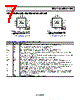
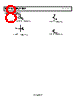
7 / 14 page  Data Sheet HMC674LC3C/HMC674LP3E Rev. K | Page 7 of 14 PIN CONFIGURATIONS AND FUNCTION DESCRIPTIONS 12 11 10 1 3 4 9 2 VTP INP INN VTN VCCO Q Q VCCO VEE PACKAGE BASE NOTES 1. NIC = NOT INTERNALLY CONNECTED. CONNECT THIS PIN TO GROUND FOR IMPROVED NOISE. 2. EXPOSED PAD. THE EXPOSED PAD MUST BE CONNECTED TO VEE. HMC674LC3C TOP VIEW (Not to Scale) Figure 3. HMC674LC3C Pin Configuration 12 11 10 1 3 4 9 2 VTP INP INN VTN VCCO Q Q VCCO HMC674LP3E TOP VIEW (Not to Scale) VEE PACKAGE BASE NOTES 1. NIC = NOT INTERNALLY CONNECTED. CONNECT THIS PIN TO GROUND FOR IMPROVED NOISE. 2. EXPOSED PAD. THE EXPOSED PAD MUST BE CONNECTED TO VEE. Figure 4. HMC674LP3E Pin Configuration Table 8. HMC674LC3C/HMC674LP3E Pin Function Descriptions Pin No. Mnemonic Description 1 VTP Termination Resistor Return Pin for VP Input. See Figure 5 for the interface schematic. 2 INP Noninverting Analog Input. See Figure 5 for the interface schematic. 3 INN Inverting Analog Input. See Figure 5 for the interface schematic. 4 VTN Termination Resistor Return Pin for VN Input. See Figure 5 for the interface schematic. 5, 16 VCCI Positive Supply Voltage Input Stage. See Figure 6 for the interface schematic. 6 LE Latch Enable Input Pin, Inverting Side. See the Theory of Operation section for additional information. See Figure 6 for the interface schematic. 7 LE Latch Enable Input Pin, Noninverting Side. See the Theory of Operation section for additional information. See Figure 6 for the interface schematic. 8 NIC Not Internally Connected. Connect this pin to ground for improved noise. 9, 12 VCCO Positive Supply Voltage for the Output Stage. See Figure 7 for the interface schematic. 10 Q Inverting Output. Q is at logic low if the analog voltage at the noninverting input, INP, is greater than the analog voltage at the inverting input, INN, provided that the comparator is in track mode. See the Theory of Operation section for additional information. See Figure 7 for the interface schematic. 11 Q Noninverting Output. Q is at logic high if the analog voltage at the noninverting input, INP, is greater than the analog voltage at the inverting input, INN, provided that the comparator is in track mode. See the Theory of Operation section for additional information. See Figure 7 for the interface schematic. 13 VEE Negative Power Supply, −3 V. See Figure 6 for the interface schematic. 14 HYS Hysteresis Control Pin. Leave this pin disconnected for zero hysteresis. Connect this pin to VEE with a resistor to add the desired amount of hysteresis. See Figure 12 to determine the correct size of the RHYS hysteresis control resistor. See Figure 8 for the interface schematic. 15 RTN Return for ESD Protection. EPAD Exposed Pad. The exposed pad must be connected to VEE. |
|
|
Link URL |
| Does ALLDATASHEET help your business so far? [ DONATE ] |
About Alldatasheet | Advertisement | Contact us | Privacy Policy | Link to Datasheet | Link Exchange | Manufacturer List All Rights Reserved©Alldatasheet.com |
| Russian : Alldatasheetru.com | Korean : Alldatasheet.co.kr | Spanish : Alldatasheet.es | French : Alldatasheet.fr | Italian : Alldatasheetit.com Portuguese : Alldatasheetpt.com | Polish : Alldatasheet.pl | Vietnamese : Alldatasheet.vn Indian : Alldatasheet.in | Mexican : Alldatasheet.com.mx | British : Alldatasheet.co.uk | New Zealand : Alldatasheet.co.nz |
|
Family Site : ic2ic.com |
icmetro.com |
 English ▼
 English
 Chinese
 German
 Japanese
 Russian
 Korean
 Spanish
 French
 Italian
 Portuguese
 Polish
 Vietnamese
 Indian
 Mexican
 British
 New Zealand