|
Electronic Components Datasheet Search |
|
|
Electronic Components Datasheet Search |
|
TC1303B-AO2EUN Datasheet(PDF) 17 Page - Microchip Technology |
|
|
|||||||||||||||||||||||||||||
TC1303B-AO2EUN Datasheet(HTML) 17 Page - Microchip Technology |
|
|
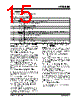
17 / 30 page  © 2005 Microchip Technology Inc. DS21949A-page 17 TC1303B 4.4 Power-Good A power-good (PG) output signal is generated based off of the LDO output voltage (VOUT2). A fixed delay time of approximately 300 ms is generated once the LDO output voltage is above the power-good threshold (typically 94% of VOUT2). As VOUT2 falls out of regula- tion, the falling PG threshold is typically 92% of VOUT2. The PG output signal is pulled up to VOUT2 indicating that power is good and pulled low indicating that VOUT2 is out of regulation. The typical quiescent current draw for power-good circuitry is less than 10 µA. If the LDO output voltage falls below the power-good threshold, the power-good output will transition to the low state. The power-good circuitry has a 165 µs delay when detecting a falling output voltage. This helps to increase the noise immunity of the power-good output and avoiding false triggering of the PG signal during line and load transients. FIGURE 4-1: Power-Good Timing. 4.5 Soft Start Both outputs of the TC1303B are controlled during startup. Less than 1% of VOUT1 or VOUT2 overshoot is observed during startup from VIN rising above the UVLO voltage or SHDN1 or SHDN2 being enabled. 4.6 Overtemperature Protection The TC1303B has an integrated overtemperature protection circuit that monitors the device junction temperature and shuts the device off if the junction tem- perature exceeds the typical 165°C threshold. If the overtemperature threshold is reached, the soft start is reset so that once the junction temperature cools to approximately 155°C, the device will automatically restart. tRPU tRPD VTH_H VOUT2 PG VOL VOH |
|
Link URL |
| Does ALLDATASHEET help your business so far? [ DONATE ] |
About Alldatasheet | Advertisement | Contact us | Privacy Policy | Link to Datasheet | Link Exchange | Manufacturer List All Rights Reserved©Alldatasheet.com |
| Russian : Alldatasheetru.com | Korean : Alldatasheet.co.kr | Spanish : Alldatasheet.es | French : Alldatasheet.fr | Italian : Alldatasheetit.com Portuguese : Alldatasheetpt.com | Polish : Alldatasheet.pl | Vietnamese : Alldatasheet.vn Indian : Alldatasheet.in | Mexican : Alldatasheet.com.mx | British : Alldatasheet.co.uk | New Zealand : Alldatasheet.co.nz |
|
Family Site : ic2ic.com |
icmetro.com |
 English ▼
 English
 Chinese
 German
 Japanese
 Russian
 Korean
 Spanish
 French
 Italian
 Portuguese
 Polish
 Vietnamese
 Indian
 Mexican
 British
 New Zealand