|
Electronic Components Datasheet Search |
|
|
Electronic Components Datasheet Search |
|
STM32U073RCU6 Datasheet(PDF) 9 Page - STMicroelectronics |
|
|
|||||||||||||||||||||||||||||
STM32U073RCU6 Datasheet(HTML) 9 Page - STMicroelectronics |
|
|
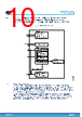
9 / 146 page  The embedded SRAM is split between two regions, as follows: • SRAM1: 32 Kbytes with hardware parity check, mapped at address 0x2000 0000 • SRAM2: 8 Kbytes with hardware parity check, located at address 0x1000 0000 SRAM2 is also mapped at address 0x2000 8000, offering a contiguous address space with SRAM1 (8 Kbytes aliased by bit band). The content of SRAM2 is retained in Standby mode. It is write-protected with a 1-Kbyte granularity. The memory can be read/write-accessed at CPU clock speed, with 0 wait states. 3.5 Boot modes At startup, the boot pin and boot selector option bit are used to select one of the three boot options: • Boot from user flash memory • Boot from system memory • Boot from embedded SRAM The boot pin is shared with a standard GPIO and can be enabled through the boot selector option bit. The boot loader is located in system memory. It manages the flash memory reprogramming through one of the following interfaces: • USART on pins PA9/PA10, PC10/PC11, or PA2/PA3 • I2C-bus on pins PB6/PB7 or PB10/PB11 • SPI on pins PA4/PA5/PA6/PA7 or PB12/PB13/PB14/PB15 • USB on pins PA11/12 3.6 Power supply management 3.6.1 Power supply schemes The STM32U073x8/B/C devices require a 1.71 to 3.6 V operating supply voltage (VDD). Several different power supplies are provided to specific peripherals: • VDD = 1.71 to 3.6 V: external power supply for I/Os (VDDIO1), the internal regulator and the system analog such as reset, power management and internal clocks. It is provided externally through VDD pins. • VDDA = 1.62 V (ADC/COMP)/1.80 V (DAC/OPAMP)/2.4 V (VREFBUF) to 3.6 V: external analog power supply for ADC, OPAMP, DAC, and comparator. The VDDA voltage level is independent from the VDD voltage. • VDDUSB = 3.0 to 3.6 V: external independent power supply for USB transceivers. The VDDUSB voltage level is independent from the VDD voltage. • VBAT = 1.55 to 3.6 V: power supply for RTC, external clock 32 kHz oscillator and backup registers (through power switch) when VDD is not present. When VBAT pin is not available on the package, VBAT pad is internally bonded to VDD/VDDA pin. • VREF+ is the analog peripheral input reference voltage, or the output of the internal voltage reference buffer (when enabled). When VDDA < 2 V, VREF+ must be equal to VDDA. When VDDA ≥ 2 V, VREF+ must be between 2 V and VDDA. It can be grounded when the analog peripherals using VREF+ are not active. The internal voltage reference buffer supports two output voltages, which is configured with VRS bit of the VREFBUF_CSR register: – VREF+ around 2.048 V (requiring VDDA equal to or higher than 2.4 V) – VREF+ around 2.5 V (requiring VDDA equal to or higher than 2.8 V) VREF+ is delivered through VREF+ pin. On packages without VREF+ pin, VREF+ is internally connected to VDDA, and the internal voltage reference buffer must be kept disabled (refer to datasheets for package pinout description). • VCORE An embedded linear voltage regulator is used to supply the VCORE internal digital power. VCORE is the power supply for digital peripherals, SRAM and flash memory. The flash memory is also supplied with VDD. STM32U073x8/B/C Functional overview DS14548 - Rev 2 page 9/146 |
|
Link URL |
| Does ALLDATASHEET help your business so far? [ DONATE ] |
About Alldatasheet | Advertisement | Contact us | Privacy Policy | Link to Datasheet | Link Exchange | Manufacturer List All Rights Reserved©Alldatasheet.com |
| Russian : Alldatasheetru.com | Korean : Alldatasheet.co.kr | Spanish : Alldatasheet.es | French : Alldatasheet.fr | Italian : Alldatasheetit.com Portuguese : Alldatasheetpt.com | Polish : Alldatasheet.pl | Vietnamese : Alldatasheet.vn Indian : Alldatasheet.in | Mexican : Alldatasheet.com.mx | British : Alldatasheet.co.uk | New Zealand : Alldatasheet.co.nz |
|
Family Site : ic2ic.com |
icmetro.com |
 English ▼
 English
 Chinese
 German
 Japanese
 Russian
 Korean
 Spanish
 French
 Italian
 Portuguese
 Polish
 Vietnamese
 Indian
 Mexican
 British
 New Zealand