|
Electronic Components Datasheet Search |
|
|
Electronic Components Datasheet Search |
|
HD6432138SW Datasheet(PDF) 36 Page - Renesas Technology Corp |
|
|
|||||||||||||||||||||||||||||
HD6432138SW Datasheet(HTML) 36 Page - Renesas Technology Corp |
|
|
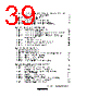
36 / 1061 page  Rev. 4.00 Jun 06, 2006 page xxxvi of liv Figure 4.2 Reset Sequence (Mode 3) .................................................................................. 95 Figure 4.3 Reset Sequence (Mode 1) .................................................................................. 96 Figure 4.4 Interrupt Sources and Number of Interrupts ...................................................... 97 Figure 4.5 (1) Stack Status after Exception Handling (Normal Mode) .................................... 99 Figure 4.5 (2) Stack Status after Exception Handling (Advanced Mode) ................................ 99 Figure 4.6 Operation When SP Value Is Odd ..................................................................... 100 Section 5 Interrupt Controller Figure 5.1 Block Diagram of Interrupt Controller .............................................................. 102 Figure 5.2 Relationship between Interrupts IRQ6, Interrupts KIN7 to KIN0, and Registers KMIMR ...................................................................................... 110 Figure 5.3 Block Diagram of Interrupts IRQ7 to IRQ0 ...................................................... 114 Figure 5.4 Timing of IRQnF Setting................................................................................... 114 Figure 5.5 Block Diagram of Address Break Function....................................................... 118 Figure 5.6 Examples of Address Break Timing.................................................................. 120 Figure 5.7 Block Diagram of Interrupt Control Operation ................................................. 122 Figure 5.8 Flowchart of Procedure Up to Interrupt Acceptance in Interrupt Control Mode 0............................................................................................................... 125 Figure 5.9 Example of State Transitions in Interrupt Control Mode 1 ............................... 126 Figure 5.10 Flowchart of Procedure Up to Interrupt Acceptance in Interrupt Control Mode 1 ................................................................................................. 128 Figure 5.11 Interrupt Exception Handling ............................................................................ 130 Figure 5.12 Contention between Interrupt Generation and Disabling .................................. 132 Figure 5.13 Interrupt Control for DTC ................................................................................. 134 Section 6 Bus Controller Figure 6.1 Block Diagram of Bus Controller...................................................................... 138 Figure 6.2 IOS Signal Output Timing................................................................................. 145 Figure 6.3 Access Sizes and Data Alignment Control (8-Bit Access Space)...................... 146 Figure 6.4 Access Sizes and Data Alignment Control (16-Bit Access Space).................... 147 Figure 6.5 Bus Timing for 8-Bit 2-State Access Space ...................................................... 149 Figure 6.6 Bus Timing for 8-Bit 3-State Access Space ...................................................... 150 Figure 6.7 Example of Wait State Insertion Timing ........................................................... 152 Figure 6.8 (a) Example of Burst ROM Access Timing (When AST = BRSTS1 = 1).............. 154 Figure 6.8 (b) Example of Burst ROM Access Timing (When AST = BRSTS1 = 0).............. 154 Figure 6.9 Example of Idle Cycle Operation ...................................................................... 156 Section 7 Data Transfer Controller [H8S/2138 Group] Figure 7.1 Block Diagram of DTC ..................................................................................... 160 Figure 7.2 Flowchart of DTC Operation............................................................................. 169 Figure 7.3 Block Diagram of DTC Activation Source Control .......................................... 172 |
|
Link URL |
| Does ALLDATASHEET help your business so far? [ DONATE ] |
About Alldatasheet | Advertisement | Contact us | Privacy Policy | Link to Datasheet | Link Exchange | Manufacturer List All Rights Reserved©Alldatasheet.com |
| Russian : Alldatasheetru.com | Korean : Alldatasheet.co.kr | Spanish : Alldatasheet.es | French : Alldatasheet.fr | Italian : Alldatasheetit.com Portuguese : Alldatasheetpt.com | Polish : Alldatasheet.pl | Vietnamese : Alldatasheet.vn Indian : Alldatasheet.in | Mexican : Alldatasheet.com.mx | British : Alldatasheet.co.uk | New Zealand : Alldatasheet.co.nz |
|
Family Site : ic2ic.com |
icmetro.com |
 English ▼
 English
 Chinese
 German
 Japanese
 Russian
 Korean
 Spanish
 French
 Italian
 Portuguese
 Polish
 Vietnamese
 Indian
 Mexican
 British
 New Zealand