|
Electronic Components Datasheet Search |
|
|
Electronic Components Datasheet Search |
|
ISL6334DIRZ Datasheet(PDF) 17 Page - Intersil Corporation |
|
|
|||||||||||||||||||||||||||||
ISL6334DIRZ Datasheet(HTML) 17 Page - Intersil Corporation |
|
|
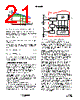
17 / 28 page  17 FN6802.2 August 31, 2010 Once the desired output offset voltage has been determined, use Equations 8 and 9 to calculate ROFS: For Positive Offset (connect ROFS to VCC): For Negative Offset (connect ROFS to GND): Dynamic VID Modern microprocessors need to make changes to their core voltage as part of normal operation. They direct the core-voltage regulator to do this by making changes to the VID inputs during regulator operation. The power management solution is required to monitor the DAC inputs and respond to on-the-fly VID changes in a controlled manner. Supervising the safe output voltage transition within the DAC range of the processor without discontinuity or disruption is a necessary function of the core-voltage regulator. In order to ensure the smooth transition of output voltage during VID change, a VID step change smoothing network, composed of RREF and CREF, as shown in Figure 7, can be used. The selection of RREF is based on the desired offset voltage, as detailed in “Output-Voltage Offset Programming” on page 16. The selection of CREF is based on the time duration for 1-bit VID change and the allowable delay time. Assuming the microprocessor controls the VID change at 1-bit every tVID, the relationship between the time constant of RREF and CREF network and tVID is given by Equation 10. During dynamic VID transition and VID step-up, the overcurrent trip point increases by 140% to avoid falsely triggering OCP circuits, while the overvoltage trip point is set to its maximum VID OVP trip level. If the dynamic VID occurs at PSI# asserted, the system should exit PSI# and complete the transition, and then resume PSI# operation 50µs after the transition. Operation Initialization Prior to converter initialization, proper conditions must exist on the enable inputs and VCC. When the conditions are met, the controller begins soft-start. Once the output voltage is within the proper window of operation, VR_RDY asserts logic high. Enable and Disable While in shutdown mode, the PWM outputs are held in a high-impedance state to assure the drivers remain off. The following input conditions must be met before the ISL6334D is released from shutdown mode. 1. The bias voltage applied at VCC must reach the internal power-on reset (POR) rising threshold. Once this threshold is reached, proper operation of all aspects of the ISL6334D are guaranteed. Hysteresis between the rising and falling thresholds assure that once enabled, ISL6334D will not inadvertently turn off unless the bias voltage drops substantially (see “Electrical Specifications” table beginning on page 6). 2. The ISL6334D features an enable input (EN_PWR) for power sequencing between the controller bias voltage and another voltage rail. The enable comparator holds the ISL6334D in shutdown until the voltage at EN_PWR rises above 0.875V. The enable comparator has about 130mV of hysteresis to prevent bounce. It is important that the driver reaches its POR level before the ISL6334D becomes enabled. The schematic in Figure 8 demonstrates sequencing the ISL6334D with the ISL66xx family of Intersil MOSFET drivers, which require 12V bias. 3. The voltage on EN_VTT must be higher than 0.875V to enable the controller. This pin is typically connected to the output of VTT VR. When all conditions previously mentioned are satisfied, ISL6334D begins the soft-start and ramps the output voltage to 1.1V first. After remaining at 1.1V for some time, ISL6334D reads the VID code at VID input pins. If the VID code is valid, ISL6334D will regulate the output to the final VID setting. If the VID code is OFF code, ISL6334D will shut down, and cycling VCC, EN_PWR or EN_VTT is needed to restart. DYNAMIC VID D/A E/A VCC DAC FB REF OFS VCC GND + - + - 0.4V 1.6V OR GND ROFS RREF ISL6334D FIGURE 7. OUTPUT VOLTAGE OFFSET PROGRAMMING CREF ROFS 1.6 RREF × VOFFSET ------------------------------ = (EQ. 8) ROFS 0.4 RREF × VOFFSET ------------------------------ = (EQ. 9) CREF RREF tVID = (EQ. 10) ISL6334D |
|
Link URL |
| Does ALLDATASHEET help your business so far? [ DONATE ] |
About Alldatasheet | Advertisement | Contact us | Privacy Policy | Link to Datasheet | Link Exchange | Manufacturer List All Rights Reserved©Alldatasheet.com |
| Russian : Alldatasheetru.com | Korean : Alldatasheet.co.kr | Spanish : Alldatasheet.es | French : Alldatasheet.fr | Italian : Alldatasheetit.com Portuguese : Alldatasheetpt.com | Polish : Alldatasheet.pl | Vietnamese : Alldatasheet.vn Indian : Alldatasheet.in | Mexican : Alldatasheet.com.mx | British : Alldatasheet.co.uk | New Zealand : Alldatasheet.co.nz |
|
Family Site : ic2ic.com |
icmetro.com |
 English ▼
 English
 Chinese
 German
 Japanese
 Russian
 Korean
 Spanish
 French
 Italian
 Portuguese
 Polish
 Vietnamese
 Indian
 Mexican
 British
 New Zealand