 |
Electronic Components Datasheet Search |
|
|
Electronic Components Datasheet Search |
|
The question interval is too short.
Please try again in a few seconds.

Hello, Please ask a question about 83C752 Datasheet
# Example questions:
➢ The text mentions an interrupt being asserted upon pwm counter overflow. what condition must be met for this interrupt to actually trigger (i.e. what must *not* be happening)?
➢ Describe how the pulse width modulation (pwm) output’s duty cycle is determined according to the text.
➢ What are the two primary functions associated with port 1? (list both)
| Part No. | 83C752 |
| Manufacturer | PHILIPS |
| Size | 225 Kbytes |
| Pages | 24 pages |
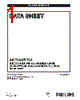
| Description | 80C51 8-bit microcontroller family 2K/64 OTP/ROM, 5 channel 8 bit A/D, I2C, PWM, low pin count |







Okay, here's a breakdown of the key information from the provided text, summarizing the features of the 83C752 microcontroller. I'll organize it into sections for clarity.
1. Core Features & Overview
️· Memory: 2K bytes of on-chip OTP ROM (One-Time Programmable Read-Only Memory).
️· Architecture: Based on the 80C51 architecture but with modifications and additions.
️· Focus: Designed for applications needing serial communication, analog input, and pulse-width modulation.
2. Key Peripherals & Communication
️· I²C Serial Communication: Replaces the UART found in the standard 80C51. Includes hardware support for multi-master and slave operations, digital filtering, and a timer for bus monitoring.
️· A/D Converter: 5-channel analog-to-digital converter with input pins on Port 1 (ADC0-ADC4).
️· PWM Output: Pulse-Width Modulation output on Port 0.4, programmable duty cycle and frequency. Can also function as an interval timer.
️· Counter/Timer: One 16-bit counter/timer with auto-reload features.
️· Interrupts: 7-source, fixed-priority interrupt system.
3. Port Configurations
️· Port 0: Open-drain outputs except for P0.4 which is PWM output and P0.0 & P0.1 are I²C communication lines (SCL & SDA).
️· Port 1: Bidirectional I/O pins, with alternate functions as analog inputs for the A/D converter, and external interrupt/timer inputs.
️· Port 3: Standard bidirectional I/O port.
4. Important Registers & Control
️· Interrupt Enable Register (IE): Modified to reflect the different interrupt sources available on the 83C752.
️· PWM Registers: Used to control the PWM output frequency, duty cycle, and enable/disable the PWM function.
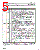
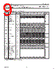
️· Special Function Registers (SFRs): A table (Table 2 in the document) lists the available special function registers and their functions.
5. Key Capabilities & Advantages
️· Serial Communication: The I²C interface simplifies communication with other devices.
️· Analog Input: The A/D converter allows for interfacing with sensors and other analog signals.
️· PWM Control: The PWM output provides precise control over power delivery and motor speed.
️· Compact Design: Integrates several peripherals into a single chip, reducing system complexity.
Let me know if you'd like me to elaborate on a specific section or aspect of the 83C752!
1. Core Features & Overview
️· Memory: 2K bytes of on-chip OTP ROM (One-Time Programmable Read-Only Memory).
️· Architecture: Based on the 80C51 architecture but with modifications and additions.
️· Focus: Designed for applications needing serial communication, analog input, and pulse-width modulation.
2. Key Peripherals & Communication
️· I²C Serial Communication: Replaces the UART found in the standard 80C51. Includes hardware support for multi-master and slave operations, digital filtering, and a timer for bus monitoring.
️· A/D Converter: 5-channel analog-to-digital converter with input pins on Port 1 (ADC0-ADC4).
️· PWM Output: Pulse-Width Modulation output on Port 0.4, programmable duty cycle and frequency. Can also function as an interval timer.
️· Counter/Timer: One 16-bit counter/timer with auto-reload features.
️· Interrupts: 7-source, fixed-priority interrupt system.
3. Port Configurations
️· Port 0: Open-drain outputs except for P0.4 which is PWM output and P0.0 & P0.1 are I²C communication lines (SCL & SDA).
️· Port 1: Bidirectional I/O pins, with alternate functions as analog inputs for the A/D converter, and external interrupt/timer inputs.
️· Port 3: Standard bidirectional I/O port.
4. Important Registers & Control
️· Interrupt Enable Register (IE): Modified to reflect the different interrupt sources available on the 83C752.
️· PWM Registers: Used to control the PWM output frequency, duty cycle, and enable/disable the PWM function.
️· Special Function Registers (SFRs): A table (Table 2 in the document) lists the available special function registers and their functions.
5. Key Capabilities & Advantages
️· Serial Communication: The I²C interface simplifies communication with other devices.
️· Analog Input: The A/D converter allows for interfacing with sensors and other analog signals.
️· PWM Control: The PWM output provides precise control over power delivery and motor speed.
️· Compact Design: Integrates several peripherals into a single chip, reducing system complexity.
| Part No. | 83C752 |
| Manufacturer | PHILIPS |
| Size | 225 Kbytes |
| Pages | 24 pages |
| Description | 80C51 8-bit microcontroller family 2K/64 OTP/ROM, 5 channel 8 bit A/D, I2C, PWM, low pin count |
| Does ALLDATASHEET help your business so far? [ DONATE ] |
About Alldatasheet | Advertisement | Contact us | Privacy Policy | Link to Datasheet | Link Exchange | Manufacturer List All Rights Reserved©Alldatasheet.com |
| Russian : Alldatasheetru.com | Korean : Alldatasheet.co.kr | Spanish : Alldatasheet.es | French : Alldatasheet.fr | Italian : Alldatasheetit.com Portuguese : Alldatasheetpt.com | Polish : Alldatasheet.pl | Vietnamese : Alldatasheet.vn Indian : Alldatasheet.in | Mexican : Alldatasheet.com.mx | British : Alldatasheet.co.uk | New Zealand : Alldatasheet.co.nz |
|
Family Site : ic2ic.com |
icmetro.com |
 English ▼
  Chinese
 German
 Japanese
 Russian
 Korean
 Spanish
 French
 Italian
 Portuguese
 Polish
 Vietnamese
 Indian
 Mexican
 British
 New Zealand