 |
Electronic Components Datasheet Search |
|
|
Electronic Components Datasheet Search |
|
The question interval is too short.
Please try again in a few seconds.

Hello, Please ask a question about LTC1540CS8 Datasheet
# Example questions:
➢ What components are commonly used in conjunction with the ltc1540 to create a hysteresis effect (e.g., positive feedback)?
➢ What is the role of components r1, r2, c1 in the circuit configurations shown, and how do they relate to adjusting the comparator's behavior (e.g., response time, hysteresis)?
➢ What is the typical supply voltage (v+) range for the ltc1540 comparator, as indicated in the provided document snippets?
| Part No. | LTC1540CS8 |
| Manufacturer | LINER |
| Size | 147 Kbytes |
| Pages | 12 pages |
| Description | Nanopower Comparator with Reference |

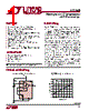
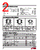
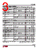
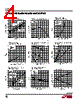
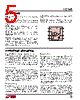
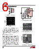
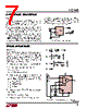
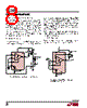
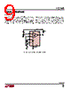
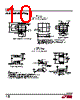


1. Overall Document Structure & Likely Purpose:
It appears to be a scan of technical documentation, most likely a datasheet or application note related to the LTC1540 comparator/voltage supervisor. The documents are presented in a mixed format: tables, circuit diagrams, textual descriptions, and various numbering schemes. It's likely this is trying to combine multiple documents or sections into a single scan. The fragmented nature suggests multiple pages scanned and compiled without optimal alignment.
2. Key Identified Data – Organized by Likely Sections
I'll attempt to organize the extracted information by what seem to be logical sections. This is difficult due to the fragmented nature of the scan. I'm presenting it in the order I perceive it appears in the scans.
A. Electrical Characteristics/Tables (Fragmented – difficult to reconstruct fully)
️· V+ LTC1540 (This likely refers to a voltage supply of 5V)
️· IN+ / IN– (Inputs to the comparator; references to REF and HYST indicate hysteresis)
️· V– GND (Ground reference voltage, presumed 0V)
️· Various column labels: "TA" (Ambient Temperature, referenced as 25°C), possibly labels for voltage levels and currents
️· Table entries showing values with seemingly no discernible context: "5, 5, 5" , "2, 4"
️· Table labels "R1, C1" indicating components and their values: R1 = 430Ω, C1 = 1µF
B. Circuit Diagrams/Application Notes (Highly Fragmented)
️· R2 10k (Resistor value, likely part of a feedback network or bias circuit)
️· R3 2.4M (Another resistor, possibly for setting the input threshold)
️· R4, R5 resistors as part of a circuit
️· "R4 2.4M 1%" and R5 = 430Ω 5%.
️· "R2 10k"
️· C1 1µF (Capacitance value, part of a filtering or compensation circuit)
️· A circuit with components R4, R5, C1, R2 and R3
C. Descriptive Text (Fragmented and Difficult to Interpret)
️· References to "HYST" (Hysteresis) – indicating a non-ideal comparator operation.
️· References to "REF" (Reference voltage)
️· Phrases like "OUT, PUT" possibly related to circuit output stages.
️· Phrases like "tP LH, tP HL" related to propagation delay.
️· Phrases referring to components, such as "R1", "R2"
D. Possible Layout Notes
️· References to "R2", "R3", "R4", and "R5" components
️· References to "TA = 25°C"
E. Table with Possible Component Values
️· Table header: “IN–” and “IN–”
️· Column 5 with "5, 5, 5"
️· A circuit configuration where R3 has a value of 15k and R4 has a value of 2.4M
F. Table Headers
*"OUT, PUT"*, “*tP HL*", *"*tP LH*”*
3. Identified Components:
Based on the information, the following components are likely present:
️· Resistors: R1 (430Ω), R2 (10k), R3 (15k, 2.4M), R4 (2.4M), R5(430Ω)
️· Capacitor: C1 (1µF)
4. Critical Limitations and Notes (PLEASE READ CAREFULLY)
️· Poor Image Quality & Fragmentation: The scan quality is very low, with significant noise, distortion, and fragmentation. This makes accurate extraction extremely challenging.
️· Missing Context: Crucially, I lack the context of the original document. Without knowing the original purpose, layout, and numbering scheme, interpreting the data is highly speculative.
️· Ambiguous Units: Units are largely missing. Values could be voltage, current, resistance, capacitance, or time, and without context, it's impossible to know for sure.
️· Fragmented Tables: The tables are broken into pieces, making it impossible to reconstruct them accurately. This significantly impacts the ability to understand the relationships between values.
️· Text Orientation: Some text sections may be rotated or at odd angles, making them difficult to read.
️· OCR Errors: OCR (Optical Character Recognition) errors are inevitable with poor-quality scans. This leads to incorrect character recognition.
️· Limited Understanding of Circuit Design: I can identify components and values, but I cannot fully understand the purpose or function of the circuit.
️· Speculative Interpretation: My interpretation is based on the limited information available. It’s highly likely that some of my interpretations are incorrect.
️· Non-Standard Formatting: The document’s formatting is inconsistent, making it difficult to establish clear relationships between different sections.
To improve the accuracy of data extraction, I would need:
️· Higher-quality scans
️· The original document (PDF or Word file)
️· Information about the document's purpose and layout
️· Expert knowledge of comparator/voltage supervisor circuits.
In summary, while I have attempted to extract and organize the data, the limitations are significant. This is more of an educated guess based on the fragments provided. The information should be treated with considerable caution.
1. Overall Document Structure & Likely Purpose:
It appears to be a scan of technical documentation, most likely a datasheet or application note related to the LTC1540 comparator/voltage supervisor. The documents are presented in a mixed format: tables, circuit diagrams, textual descriptions, and various numbering schemes. It's likely this is trying to combine multiple documents or sections into a single scan. The fragmented nature suggests multiple pages scanned and compiled without optimal alignment.
2. Key Identified Data – Organized by Likely Sections
I'll attempt to organize the extracted information by what seem to be logical sections. This is difficult due to the fragmented nature of the scan. I'm presenting it in the order I perceive it appears in the scans.
A. Electrical Characteristics/Tables (Fragmented – difficult to reconstruct fully)
️· V+ LTC1540 (This likely refers to a voltage supply of 5V)
️· IN+ / IN– (Inputs to the comparator; references to REF and HYST indicate hysteresis)
️· V– GND (Ground reference voltage, presumed 0V)
️· Various column labels: "TA" (Ambient Temperature, referenced as 25°C), possibly labels for voltage levels and currents
️· Table entries showing values with seemingly no discernible context: "5, 5, 5" , "2, 4"
️· Table labels "R1, C1" indicating components and their values: R1 = 430Ω, C1 = 1µF
B. Circuit Diagrams/Application Notes (Highly Fragmented)
️· R2 10k (Resistor value, likely part of a feedback network or bias circuit)
️· R3 2.4M (Another resistor, possibly for setting the input threshold)
️· R4, R5 resistors as part of a circuit
️· "R4 2.4M 1%" and R5 = 430Ω 5%.
️· "R2 10k"
️· C1 1µF (Capacitance value, part of a filtering or compensation circuit)
️· A circuit with components R4, R5, C1, R2 and R3
C. Descriptive Text (Fragmented and Difficult to Interpret)
️· References to "HYST" (Hysteresis) – indicating a non-ideal comparator operation.
️· References to "REF" (Reference voltage)
️· Phrases like "OUT, PUT" possibly related to circuit output stages.
️· Phrases like "tP LH, tP HL" related to propagation delay.
️· Phrases referring to components, such as "R1", "R2"
D. Possible Layout Notes
️· References to "R2", "R3", "R4", and "R5" components
️· References to "TA = 25°C"
E. Table with Possible Component Values
️· Table header: “IN–” and “IN–”
️· Column 5 with "5, 5, 5"
️· A circuit configuration where R3 has a value of 15k and R4 has a value of 2.4M
F. Table Headers
*"OUT, PUT"*, “*tP HL*", *"*tP LH*”*
3. Identified Components:
Based on the information, the following components are likely present:
️· Resistors: R1 (430Ω), R2 (10k), R3 (15k, 2.4M), R4 (2.4M), R5(430Ω)
️· Capacitor: C1 (1µF)
4. Critical Limitations and Notes (PLEASE READ CAREFULLY)
️· Poor Image Quality & Fragmentation: The scan quality is very low, with significant noise, distortion, and fragmentation. This makes accurate extraction extremely challenging.
️· Missing Context: Crucially, I lack the context of the original document. Without knowing the original purpose, layout, and numbering scheme, interpreting the data is highly speculative.
️· Ambiguous Units: Units are largely missing. Values could be voltage, current, resistance, capacitance, or time, and without context, it's impossible to know for sure.
️· Fragmented Tables: The tables are broken into pieces, making it impossible to reconstruct them accurately. This significantly impacts the ability to understand the relationships between values.
️· Text Orientation: Some text sections may be rotated or at odd angles, making them difficult to read.
️· OCR Errors: OCR (Optical Character Recognition) errors are inevitable with poor-quality scans. This leads to incorrect character recognition.
️· Limited Understanding of Circuit Design: I can identify components and values, but I cannot fully understand the purpose or function of the circuit.
️· Speculative Interpretation: My interpretation is based on the limited information available. It’s highly likely that some of my interpretations are incorrect.
️· Non-Standard Formatting: The document’s formatting is inconsistent, making it difficult to establish clear relationships between different sections.
To improve the accuracy of data extraction, I would need:
️· Higher-quality scans
️· The original document (PDF or Word file)
️· Information about the document's purpose and layout
️· Expert knowledge of comparator/voltage supervisor circuits.
In summary, while I have attempted to extract and organize the data, the limitations are significant. This is more of an educated guess based on the fragments provided. The information should be treated with considerable caution.
| Part No. | LTC1540CS8 |
| Manufacturer | LINER |
| Size | 147 Kbytes |
| Pages | 12 pages |
| Description | Nanopower Comparator with Reference |
| Does ALLDATASHEET help your business so far? [ DONATE ] |
About Alldatasheet | Advertisement | Contact us | Privacy Policy | Link to Datasheet | Link Exchange | Manufacturer List All Rights Reserved©Alldatasheet.com |
| Russian : Alldatasheetru.com | Korean : Alldatasheet.co.kr | Spanish : Alldatasheet.es | French : Alldatasheet.fr | Italian : Alldatasheetit.com Portuguese : Alldatasheetpt.com | Polish : Alldatasheet.pl | Vietnamese : Alldatasheet.vn Indian : Alldatasheet.in | Mexican : Alldatasheet.com.mx | British : Alldatasheet.co.uk | New Zealand : Alldatasheet.co.nz |
|
Family Site : ic2ic.com |
icmetro.com |
 English ▼
  Chinese
 German
 Japanese
 Russian
 Korean
 Spanish
 French
 Italian
 Portuguese
 Polish
 Vietnamese
 Indian
 Mexican
 British
 New Zealand