|
Electronic Components Datasheet Search |
|
|
Electronic Components Datasheet Search |
|
MP8770 Datasheet(PDF) 18 Page - Monolithic Power Systems |
|
|
|||||||||||||||||||||||||||||
MP8770 Datasheet(HTML) 18 Page - Monolithic Power Systems |
|
|
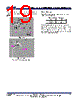
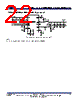
18 / 23 page  MP8770 – 17V, 8A, SYNCHRONOUS, STEP-DOWN CONVERTER MP8770 Rev. 1.0 www.MonolithicPower.com 18 1/4/2018 MPS Proprietary Information. Patent Protected. Unauthorized Photocopy and Duplication Prohibited. © 2018 MPS. All Rights Reserved. The input voltage ripple can be estimated with Equation (8): OUT OUT OUT IN SW IN IN IN I V V V (1 ) F C V V (8) The worst-case conditions occur at VIN = 2VOUT, shown in Equation (9): OUT IN SW IN I 1 V 4 F C (9) Selecting the Output Capacitor The output capacitor is required to maintain the DC output voltage. Ceramic or POSCAP capacitors are recommended. The output voltage ripple can be estimated with Equation (10): OUT OUT OUT ESR SW IN SW OUT VV 1 V (1 ) (R ) F L V 8 F C (10) In the case of ceramic capacitors, the impedance at the switching frequency is dominated by the capacitance. The output voltage ripple is mainly caused by the capacitance. For simplification, the output voltage ripple can be estimated with Equation (11): OUT OUT OUT 2 SW OUT IN VV V (1 ) 8 F L C V (11) The output voltage ripple caused by the ESR is very small. Therefore, an external ramp is needed to stabilize the system. The external ramp can be generated through a resistor (RRAMP) and capacitor (Cr). In the case of POSCAP capacitors, the ESR dominates the impedance at the switching frequency. For simplification, the output ripple can be approximated with Equation (12): OUT OUT OUT ESR SW IN VV V (1 ) R F L V (12) Besides considering the output ripple, a larger output capacitor can also result in better load transient response. Be sure to consider the maximum output capacitor limitation in the design application. If the output capacitor value is too high, the output voltage cannot reach the design value during the soft-start time and fails to regulate. The maximum output capacitor value (Co_max) can be limited approximately with Equation (20): O _ MAX LIM _ AVG OUT ss OUT C (I I ) T / V (20) Where ILIM_AVG is the average start-up current during the soft-start period, and Tss is the soft- start time. PCB Layout Guidelines Efficient PCB layout of the switching power supplies is critical for stable operation. A poor layout design can result in poor line or load regulation and stability issues. For best results, refer to Figure 8 and follow the guidelines below. 1. Place the high current paths (GND, VIN, and SW) very close to the device with short, direct, and wide traces. 2. Place the input capacitor as close to VIN and GND as possible. 3. Place a VCC decoupling capacitor close to the device. 4. Connect AGND and PGND at the point of the VCC capacitor ’s ground connection. 5. Place the external feedback resistors next to FB. 6. Keep the switching node (SW) short and away from the feedback network. |
|
|
Link URL |
| Does ALLDATASHEET help your business so far? [ DONATE ] |
About Alldatasheet | Advertisement | Contact us | Privacy Policy | Link to Datasheet | Link Exchange | Manufacturer List All Rights Reserved©Alldatasheet.com |
| Russian : Alldatasheetru.com | Korean : Alldatasheet.co.kr | Spanish : Alldatasheet.es | French : Alldatasheet.fr | Italian : Alldatasheetit.com Portuguese : Alldatasheetpt.com | Polish : Alldatasheet.pl | Vietnamese : Alldatasheet.vn Indian : Alldatasheet.in | Mexican : Alldatasheet.com.mx | British : Alldatasheet.co.uk | New Zealand : Alldatasheet.co.nz |
|
Family Site : ic2ic.com |
icmetro.com |
 English ▼
 English
 Chinese
 German
 Japanese
 Russian
 Korean
 Spanish
 French
 Italian
 Portuguese
 Polish
 Vietnamese
 Indian
 Mexican
 British
 New Zealand