|
Electronic Components Datasheet Search |
|
|
Electronic Components Datasheet Search |
|
STM32U545NET3QTR Datasheet(PDF) 39 Page - STMicroelectronics |
|
|
|||||||||||||||||||||||||||||
STM32U545NET3QTR Datasheet(HTML) 39 Page - STMicroelectronics |
|
|
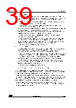
39 / 283 page  DS14216 Rev 1 39/283 STM32U545xx Functional overview 88 • Standby mode The Standby mode is used to achieve the lowest power consumption with BOR. The internal regulator is switched off so that the VCORE domain is powered off. The PLL, the MSI, the HSI16, the HSI48 and the HSE crystal oscillators are also switched off. The RTC can remain active (Standby mode with RTC, Standby mode without RTC). The BOR always remains active in Standby mode. The state of each I/O during Standby mode can be selected by software: I/O with internal pull-up, internal pull-down or floating. After entering Standby mode, SRAMs and register contents are lost except for registers and backup SRAM in the backup domain and Standby circuitry. Optionally, the full SRAM2 or 8 Kbytes or 56 Kbytes can be retained in Standby mode, supplied by the low-power regulator (Standby with SRAM2 retention mode). The BOR can be configured in ultra-low-power mode to further reduce power consumption during Standby mode. The device exits Standby mode when an external reset (NRST pin), an IWDG reset, WKUP pin event (configurable rising or falling edge), an RTC event occurs (alarm, periodic wake-up, timestamp), or a tamper detection. The tamper detection can be raised either due to external pins or due to an internal failure detection. The system clock after wake-up is MSI up to 4 MHz. • Shutdown mode The lowest power consumption is achieved in Shutdown mode. The internal regulator is switched off so that the VCORE domain is powered off. The PLL, the HSI16, the HSI48, the MSI, the LSI and the HSE oscillators are also switched off. The RTC can remain active (Shutdown mode with RTC, Shutdown mode without RTC). The BOR is not available in Shutdown mode. No power voltage monitoring is possible in this mode, therefore the switch to backup domain is not supported (VBAT). SRAMs and register contents are lost except for registers in the backup domain. The device exits Shutdown mode when an external reset (NRST pin), a WKUP pin event (configurable rising or falling edge), or an RTC event occurs (alarm, periodic wake-up, timestamp), or a tamper detection. The system clock after wake-up is MSI at 4 MHz. Low-power background autonomous mode (LPBAM) The ultra-low-power STM32U545xx devices support LPBAM (low-power background autonomous mode) that allows peripherals to be functional and autonomous in Stop mode (Stop 0, Stop 1 and Stop 2 modes), so without any software running. In Stop 0 and Stop 1 modes, the autonomous peripherals are the following: ADC4, DAC1, LPTIMx (x = 1 to 4), USARTx (x = 1, 3, 4, 5), LPUART1, SPIx (x = 1 to 3), I2Cx (x = 1 to 4), MDF1, ADF1, GPDMA1 and LPDMA1. In these modes, SRAM1, SRAM2, and SRAM4 can be accessed by the GPDMA1, and SRAM4 can be accessed by the LPDMA1. In Stop 2 mode, the autonomous peripherals are the following: ADC4, DAC1, LPTIM1, LPTIM3, LPTIM4, LPUART1, SPI3, I2C3, ADF1 and LPDMA1. In this mode, the SRAM4 can be accessed by the LPDMA1. |
|
Link URL |
| Does ALLDATASHEET help your business so far? [ DONATE ] |
About Alldatasheet | Advertisement | Contact us | Privacy Policy | Link to Datasheet | Link Exchange | Manufacturer List All Rights Reserved©Alldatasheet.com |
| Russian : Alldatasheetru.com | Korean : Alldatasheet.co.kr | Spanish : Alldatasheet.es | French : Alldatasheet.fr | Italian : Alldatasheetit.com Portuguese : Alldatasheetpt.com | Polish : Alldatasheet.pl | Vietnamese : Alldatasheet.vn Indian : Alldatasheet.in | Mexican : Alldatasheet.com.mx | British : Alldatasheet.co.uk | New Zealand : Alldatasheet.co.nz |
|
Family Site : ic2ic.com |
icmetro.com |
 English ▼
 English
 Chinese
 German
 Japanese
 Russian
 Korean
 Spanish
 French
 Italian
 Portuguese
 Polish
 Vietnamese
 Indian
 Mexican
 British
 New Zealand