|
Electronic Components Datasheet Search |
|
|
Electronic Components Datasheet Search |
|
RT7277 Datasheet(PDF) 13 Page - Richtek Technology Corporation |
|
|
|||||||||||||||||||||||||||||
RT7277 Datasheet(HTML) 13 Page - Richtek Technology Corporation |
|
|
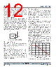
13 / 14 page  RT7277 13 DS7277-00 October 2012 www.richtek.com © Copyright 2012 Richtek Technology Corporation. All rights reserved. is a registered trademark of Richtek Technology Corporation. Figure 7. PCB Layout Guide Layout Consideration Follow the PCB layout guidelines for optimal performance of the RT7277 Keep the traces of the main current paths as short and wide as possible. Put the input capacitor as close as possible to the device pins (VIN and GND). EN FB PVCC SS VIN BOOT GND SW GND 2 3 4 5 6 7 8 9 C2 C1 C6 L1 C7 VOUT C4 C5 R1 R2 GND Input capacitor must be placed as close to the IC as possible. SW should be connected to inductor by wide and short trace. Keep sensitive components away from this trace. The resistor divider must be connected as close to the device as possible. SW node is with high frequency voltage swing and should be kept at small area. Keep sensitive components away from the SW node to prevent stray capacitive noise pickup. Connect feedback network behind the output capacitors. Keep the loop area small. Place the feedback components near the RT7277 feedback pin. The GND and Exposed Pad should be connected to a strong ground plane for heat sinking and noise protection. |
|
|
Link URL |
| Does ALLDATASHEET help your business so far? [ DONATE ] |
About Alldatasheet | Advertisement | Contact us | Privacy Policy | Link to Datasheet | Link Exchange | Manufacturer List All Rights Reserved©Alldatasheet.com |
| Russian : Alldatasheetru.com | Korean : Alldatasheet.co.kr | Spanish : Alldatasheet.es | French : Alldatasheet.fr | Italian : Alldatasheetit.com Portuguese : Alldatasheetpt.com | Polish : Alldatasheet.pl | Vietnamese : Alldatasheet.vn Indian : Alldatasheet.in | Mexican : Alldatasheet.com.mx | British : Alldatasheet.co.uk | New Zealand : Alldatasheet.co.nz |
|
Family Site : ic2ic.com |
icmetro.com |
 English ▼
 English
 Chinese
 German
 Japanese
 Russian
 Korean
 Spanish
 French
 Italian
 Portuguese
 Polish
 Vietnamese
 Indian
 Mexican
 British
 New Zealand