|
Electronic Components Datasheet Search |
|
|
Electronic Components Datasheet Search |
|
MP28253EL Datasheet(PDF) 10 Page - Monolithic Power Systems |
|
|
|||||||||||||||||||||||||||||
MP28253EL Datasheet(HTML) 10 Page - Monolithic Power Systems |
|
|
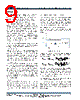
10 / 15 page  MP28253 – 3A, 21V, SYNCHRONOUS STEP-DOWN CONVERTER WITH INTERNAL MOSFETS MP28253 Rev. 1.02 www.MonolithicPower.com 10 12/25/2013 MPS Proprietary Information. Patent Protected. Unauthorized Photocopy and Duplication Prohibited. © 2013 MPS. All Rights Reserved. Vin EN/Sync Vcc Vout VEN_Rising 5us VEN_Falling VIN_STA RT 1ms VCC_Rising Turn On Delay Turn Off Delay VIN_STOP Figure 3—Startup Sequence Using EN Divider 3) Synchronized by External Sync Clock Signal The chip can be synchronized to external clock range from 300kHz up to 2MHz through this pin 2ms right after output voltage is set, with the internal clock rising edge synchronized to the external clock rising edge. Vin EN/Sync Vcc Vout CLK 5us Foldback 500kHz External CLK 0.625*Vout_set 2ms 1ms VCC_Rising Vout_set Figure 4—Startup Sequence Using External Sync Clock Signal Under-Voltage Lockout (UVLO) Under-voltage lockout (UVLO) is implemented to protect the chip from operating at insufficient supply voltage. The MP28253 UVLO comparator monitors the output voltage of the internal regulator, VCC. The UVLO rising threshold is about 4.0V while its falling threshold is a consistent 3.2V. External Soft-Start The soft-start is implemented to prevent the converter output voltage from overshooting during startup. When the chip starts, the internal circuitry generates a soft-start voltage (SS) ramping up from 0V to 1.2V. When it is lower than the internal FB reference (REF), SS overrides REF so the error amplifier uses SS as the reference. When SS is higher than REF, REF regains control. The SS time can be set by external decoupled cap. The soft-start time can be caculated as below: 5 ss Vref(V) C (nF) t(ms) 10.5 A × = μ To reduce the susceptibility to noise, do not leave SS pin open. Use a capacitor with small value if soft –start function not needed. Over-Current-Protection and Hiccup The MP28253 has cycle-by-cycle over current limit when the inductor current peak value exceeds the set current limit threshold. Meanwhile, output voltage starts to drop until FB is below the Under-Voltage (UV) threshold, typically 30% below the reference. Once a UV is triggered, the MP28253 enters hiccup mode to periodically restart the part. This protection mode is especially useful when the output is dead-short to ground. The average short circuit current is greatly reduced to alleviate the thermal issue and to protect the regulator. The MP28253 exits the hiccup mode once the over current condition is removed. Thermal Shutdown Thermal shutdown is implemented to prevent the chip from operating at exceedingly high temperatures. When the silicon die temperature is higher than 150 °C, it shuts down the whole chip. When the temperature is lower than its lower threshold, typically 140 °C, the chip is enabled again. Floating Driver and Bootstrap Charging The floating power MOSFET driver is powered by an external bootstrap capacitor. This floating driver has its own UVLO protection. This UVLO’s rising threshold is 2.2V with a hysteresis of 150mV. The bootstrap capacitor voltage is regulated internally by VIN through D1, M3, C4, L1 and C2 (Figure 5). If (VIN-VSW) is more than 5V, U2 will regulate M3 to maintain a 5V BST voltage across C4. SW Figure 5—Internal Bootstrap Charging Circuit |
|
|
Link URL |
| Does ALLDATASHEET help your business so far? [ DONATE ] |
About Alldatasheet | Advertisement | Contact us | Privacy Policy | Link to Datasheet | Link Exchange | Manufacturer List All Rights Reserved©Alldatasheet.com |
| Russian : Alldatasheetru.com | Korean : Alldatasheet.co.kr | Spanish : Alldatasheet.es | French : Alldatasheet.fr | Italian : Alldatasheetit.com Portuguese : Alldatasheetpt.com | Polish : Alldatasheet.pl | Vietnamese : Alldatasheet.vn Indian : Alldatasheet.in | Mexican : Alldatasheet.com.mx | British : Alldatasheet.co.uk | New Zealand : Alldatasheet.co.nz |
|
Family Site : ic2ic.com |
icmetro.com |
 English ▼
 English
 Chinese
 German
 Japanese
 Russian
 Korean
 Spanish
 French
 Italian
 Portuguese
 Polish
 Vietnamese
 Indian
 Mexican
 British
 New Zealand