|
Electronic Components Datasheet Search |
|
|
Electronic Components Datasheet Search |
|
AT86RF211DAI-R Datasheet(PDF) 2 Page - ATMEL Corporation |
|
|
|||||||||||||||||||||||||||||
AT86RF211DAI-R Datasheet(HTML) 2 Page - ATMEL Corporation |
|
|
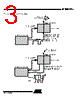
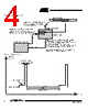
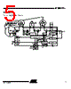
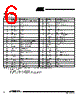
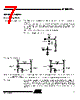
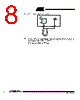
2 / 48 page  2 AT86RF211 1942C–WIRE–06/02 General Overview General Overview of Functioning The AT86RF211 is a microcontroller RF peripheral: all the user has to do is to write/read registers to setup the chip (i.e. frequency selection) or have information about parame- ters such as RSSI level, Vbattery, PLL lock state. All these operations are carried out via a three-wire serial interface. Normal Mode Thechip isset-upbythe microcontroller: frequency and mode (Rx or Tx). Then it acts like a "pipe": any data entering DATAMSG is immediately radiated (Tx) or any wanted signal collected by the aerial is demodulated, transferred to the microcontroller by the same pin DATAMSG (Rx) as reshaped bits. No data is stored or processed into the chip. See Figure 1. Note: In Rx mode, a clock recovery DATACLK is available on the digital interface to provide the microcontroller with a synchronization signal. Wake-up Mode The chip is set up in a special Rx mode called sleep mode. The chip wakes up periodi- cally thanks to its internal timer (stand alone procedure, the microcontroller is in power- down mode), waiting for an expected message previously defined. If no correct sequence is received, the periodic scan continues. If a correct message is detected, its data field is stored into the AT86RF211 (up to 32 bits) and an interrupt is generated on the WAKEUP pin. See Figure 2 and Figure 3. |
|
Link URL |
| Does ALLDATASHEET help your business so far? [ DONATE ] |
About Alldatasheet | Advertisement | Contact us | Privacy Policy | Link to Datasheet | Link Exchange | Manufacturer List All Rights Reserved©Alldatasheet.com |
| Russian : Alldatasheetru.com | Korean : Alldatasheet.co.kr | Spanish : Alldatasheet.es | French : Alldatasheet.fr | Italian : Alldatasheetit.com Portuguese : Alldatasheetpt.com | Polish : Alldatasheet.pl | Vietnamese : Alldatasheet.vn Indian : Alldatasheet.in | Mexican : Alldatasheet.com.mx | British : Alldatasheet.co.uk | New Zealand : Alldatasheet.co.nz |
|
Family Site : ic2ic.com |
icmetro.com |
 English ▼
 English
 Chinese
 German
 Japanese
 Russian
 Korean
 Spanish
 French
 Italian
 Portuguese
 Polish
 Vietnamese
 Indian
 Mexican
 British
 New Zealand