|
Electronic Components Datasheet Search |
|
|
Electronic Components Datasheet Search |
|
ADN8102ACPZ-R7 Datasheet(PDF) 24 Page - Analog Devices |
|
|
|||||||||||||||||||||||||||||
ADN8102ACPZ-R7 Datasheet(HTML) 24 Page - Analog Devices |
|
|
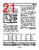
24 / 36 page  ADN8102 Rev. C | Page 24 of 36 SELECTIVE SQUELCH AND DISABLE Each transmitter is equipped with output disable and output squelch controls. Disable is a full power-down state: the trans- mitter current is reduced to zero, and the output pins pull up to VTTO, but there is a delay of approximately 1 µs associated with re-enabling the transmitter. The output disable control is accessed through the EN bit (Bit 4) of the OUT_A/OUT_B configuration registers through the I2C control interface. Squelch is not a full power-down state but a state in which only the output current is reduced to zero and the output pins pull up to VTTO, and there is a much smaller delay to bring back the output current. The output squelch and the output disable control can both be accessed through the OUT_A/OUT_B squelch control registers, with the top nibble representing the squelch control for one entire output port, and the bottom nibble representing the output disable for one entire output port. The ports are disabled or squelched by writing 0s to the corresponding nibbles. The ports are enabled by writing all 1s, which is the default setting. For example, to squelch Port A, Register 0xC3 must be set to 0x0F. The entire nibble must be written to all 0s for this functionality. Table 18. Squelch and Disable Control Registers Name Address Data Default OUT_A/ OUT_B squelch control 0xC3, 0xE3 SQUELCH[3:0] DISABLE[3:0] 0xFF Table 19. Squelch and Disable Functionality SQUELCH[3:0] DISABLE[3:0] Output State 1111 1111 Enabled (default) xxxx1 0000 Disabled 0000 1111 Squelched 1 xxxx = don’t care |
|
Link URL |
| Does ALLDATASHEET help your business so far? [ DONATE ] |
About Alldatasheet | Advertisement | Contact us | Privacy Policy | Link to Datasheet | Link Exchange | Manufacturer List All Rights Reserved©Alldatasheet.com |
| Russian : Alldatasheetru.com | Korean : Alldatasheet.co.kr | Spanish : Alldatasheet.es | French : Alldatasheet.fr | Italian : Alldatasheetit.com Portuguese : Alldatasheetpt.com | Polish : Alldatasheet.pl | Vietnamese : Alldatasheet.vn Indian : Alldatasheet.in | Mexican : Alldatasheet.com.mx | British : Alldatasheet.co.uk | New Zealand : Alldatasheet.co.nz |
|
Family Site : ic2ic.com |
icmetro.com |
 English ▼
 English
 Chinese
 German
 Japanese
 Russian
 Korean
 Spanish
 French
 Italian
 Portuguese
 Polish
 Vietnamese
 Indian
 Mexican
 British
 New Zealand