|
Electronic Components Datasheet Search |
|
|
Electronic Components Datasheet Search |
|
AD7631BSTZ Datasheet(PDF) 11 Page - Analog Devices |
|
|
|||||||||||||||||||||||||||||
AD7631BSTZ Datasheet(HTML) 11 Page - Analog Devices |
|
|
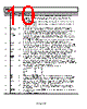
11 / 32 page  AD7631 Rev. A | Page 11 of 32 Pin No. Mnemonic Type1 Description 37 REF AO/I Reference Input/Output. When PDREF/PDBUF = low, the internal reference and buffer are enabled producing 5 V on this pin. When PDREF/PDBUF = high, the internal reference and buffer are disabled, allowing an externally supplied voltage reference up to AVDD volts. Decoupling with at least a 22 μF capacitor is required with or without the internal reference and buffer. See the Voltage Reference Input/Output section. 38 REFGND AI Reference Input Analog Ground. Connected to analog ground plane. 39 IN− AI Analog Input. Referenced to IN+. In the 0 V to 5 V input range, IN− is between 0 V and VREF V centered about VREF/2. In the 0 V to 10 V range, IN− is between 0 V and 2 VREF V centered about VREF. In the ±5 V and ±10 V ranges, IN− is true bipolar up to ±2 VREF V (±5 V range) or ±4 VREF V (±10 V range) and centered about 0 V. In all ranges, IN− must be driven 180° out of phase with IN+. 40 VCC P High Voltage Positive Supply. Normally +7 V to +15 V. 41 VEE P High Voltage Negative Supply. Normally 0 V to −15 V (0 V in unipolar ranges). 43 IN+ AI Analog Input. Referenced to IN−. In the 0 V to 5 V input range, IN+ is between 0 V and VREF V centered about VREF/2. In the 0 V to 10 V range, IN+ is between 0 V and 2 VREF V centered about VREF. In the ±5 V and ±10 V ranges, IN+ is true bipolar up to ±2 VREF V (±5 V range) or ±4 VREF V (±10 V range) and centered about 0 V. In all ranges, IN+ must be driven 180° out of phase with IN−. 45 TEMP AO Temperature Sensor Analog Output. When the internal reference is enabled (PDREF = PDBUF = low), this pin outputs a voltage proportional to the temperature of the AD7631. See the Voltage Reference Input/Output section. 46 REFBUFIN AI Reference Buffer Input. When using an external reference with the internal reference buffer (PDBUF = low, PDREF = high), applying 2.5 V on this pin produces 5 V on the REF pin. See the Voltage Reference Input/Output section. 47 PDREF DI Internal Reference Power-Down Input. When low, the internal reference is enabled. When high, the internal reference is powered down, and an external reference must be used. 48 PDBUF DI Internal Reference Buffer Power-Down Input. When low, the buffer is enabled (must be low when using internal reference). When high, the buffer is powered down. 49 EPAD3 NC Exposed Pad. The exposed pad is not connected internally. It is recommended that the pad be soldered to VEE. 1 AI = analog input; AI/O = bidirectional analog; AO = analog output; DI = digital input; DI/O = bidirectional digital; DO = digital output; P = power, NC = no internal connection. 2 In serial configuration mode (MODE[1:0] = 3, HW/SW = low), this input is programmed with the serial configuration register and this pin is a don’t care. See the Hardware Configuration section and the Software Configuraion section. 3 LFCSP_VQ package only. Table 7. Data Bus Interface Definition MODE MODE1 MODE0 D0/OB/2C D1/A0 D2/A1 D[3] D[4:9] D[10:11] D[12:15] D[16:17] Description 0 0 0 R[0] R[1] R[2] R[3] R[4:9] R[10:11] R[12:15] R[16:17] 18-bit parallel 1 0 1 OB/2C A0 = 0 R[2] R[3] R[4:9] R[10:11] R[12:15] R[16:17] 16-bit high word 1 0 1 OB/2C A0 = 1 R[0] R[1] All zeros 16-bit low word 2 1 0 OB/2C A0 = 0 A1 = 0 All High-Z R[10:11] R[12:15] R[16:17] 8-bit high byte 2 1 0 OB/2C A0 = 0 A1 = 1 All High-Z R[2:3] R[4:7] R[8:9] 8-bit midbyte 2 1 0 OB/2C A0 = 1 A1 = 0 All High-Z R[0:1] All zeros 8-bit low byte 2 1 0 OB/2C A0 = 1 A1 = 1 All High-Z All zeros R[0:1] 8-bit low byte 3 1 1 OB/2C All High-Z Serial interface Serial interface |
|
Link URL |
| Does ALLDATASHEET help your business so far? [ DONATE ] |
About Alldatasheet | Advertisement | Contact us | Privacy Policy | Link to Datasheet | Link Exchange | Manufacturer List All Rights Reserved©Alldatasheet.com |
| Russian : Alldatasheetru.com | Korean : Alldatasheet.co.kr | Spanish : Alldatasheet.es | French : Alldatasheet.fr | Italian : Alldatasheetit.com Portuguese : Alldatasheetpt.com | Polish : Alldatasheet.pl | Vietnamese : Alldatasheet.vn Indian : Alldatasheet.in | Mexican : Alldatasheet.com.mx | British : Alldatasheet.co.uk | New Zealand : Alldatasheet.co.nz |
|
Family Site : ic2ic.com |
icmetro.com |
 English ▼
 English
 Chinese
 German
 Japanese
 Russian
 Korean
 Spanish
 French
 Italian
 Portuguese
 Polish
 Vietnamese
 Indian
 Mexican
 British
 New Zealand