 |
Electronic Components Datasheet Search |
|
|
Electronic Components Datasheet Search |
|
The question interval is too short.
Please try again in a few seconds.

Hello, Please ask a question about MIC2526 Datasheet
# Example questions:
➢ What conditions will activate the fault flag (flg)?
➢ How can the usb controller address this issue, and what is the rationale behind the solution?
➢ What is the purpose of using a bypass capacitor on the input (in) of the mic2526, and what issues does it prevent?
| Part No. | MIC2526 |
| Manufacturer | MICREL |
| Size | 95 Kbytes |
| Pages | 12 pages |
| Description | Dual USB Power Control Switch Not Recommended for New Designs |









1. Product Overview:
️· What it is: The MIC2526 is a dual, high-speed power switch IC designed for USB power delivery applications (e.g., chargers, hubs, embedded systems). It acts as a controlled power switch with integrated protection features.
️· Key Benefits:
- High-speed switching for efficient power delivery.
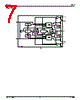
- Overcurrent protection, thermal shutdown, and undervoltage lockout.
- Soft start to limit inrush current and prevent USB voltage droop.
- Fault flag output for signaling fault conditions.
- Small footprint due to its integrated design.
2. Key Features & Protection:
️· Dual Channels: It has two independent power switches.
️· Protection Features:
- Overcurrent Protection: Limits output current to protect components.
- Thermal Shutdown: Shuts down output to prevent overheating.
- Undervoltage Lockout: Prevents operation if the input voltage is too low.
️· Fault Flag (FLG): An open-drain output that signals fault conditions (undervoltage, overcurrent, thermal shutdown).
️· Soft Start: Controlled startup to minimize inrush current and meet USB voltage droop requirements.
3. Applications:
️· USB Power Delivery: Primary focus - chargers, hubs, embedded systems that need controlled power.
️· Hot-Plug Applications: Designed to handle situations where devices are connected/disconnected while the system is powered.
️· Battery Charging: Can be used in battery charging circuits.
4. Electrical Characteristics - Important Values & Behavior:
️· Input Voltage Range: Typical range is 3.0V to 5.5V.
️· Output Current Limit: 1.6A is the typical current-limit threshold. The device enters constant-current mode at this limit.
️· Soft Start Time: Provides a controlled startup to minimize inrush current and meet USB voltage droop requirements.
️· Fault Flag Response:
- The fault flag can activate briefly (around 1ms) during startup due to inrush current.
- A 1ms RC filter or debounce routine is recommended for USB applications to ignore these transient flag activations.
5. Design Considerations and Recommendations:
️· Input Filtering: A 0.1µF to 1µF bypass capacitor is *essential* close to the IC to handle transients and ringing.
️· Enable Input: Must be driven logically high or low; floating the input is problematic.
️· Transient Filtering: A 1ms RC filter or software debounce routine is critical for USB applications to prevent spurious fault flag activations.
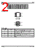
️· Package Options: Available in 8-pin SOP (plastic surface mount) and DIP (dual in-line package).
6. Key Takeaways for USB Applications:
️· Fault Flag Management is Crucial: The fault flag is sensitive during startup and transient events. Proper filtering or debouncing is mandatory.
️· Soft Start & Inrush Current: The soft-start feature reduces stress on the system and helps meet USB specifications.
️· Input Bypass Capacitor: Don't forget this! It's essential for stable operation.
1. Product Overview:
️· What it is: The MIC2526 is a dual, high-speed power switch IC designed for USB power delivery applications (e.g., chargers, hubs, embedded systems). It acts as a controlled power switch with integrated protection features.
️· Key Benefits:
- High-speed switching for efficient power delivery.
- Overcurrent protection, thermal shutdown, and undervoltage lockout.
- Soft start to limit inrush current and prevent USB voltage droop.
- Fault flag output for signaling fault conditions.
- Small footprint due to its integrated design.
2. Key Features & Protection:
️· Dual Channels: It has two independent power switches.
️· Protection Features:
- Overcurrent Protection: Limits output current to protect components.
- Thermal Shutdown: Shuts down output to prevent overheating.
- Undervoltage Lockout: Prevents operation if the input voltage is too low.
️· Fault Flag (FLG): An open-drain output that signals fault conditions (undervoltage, overcurrent, thermal shutdown).
️· Soft Start: Controlled startup to minimize inrush current and meet USB voltage droop requirements.
3. Applications:
️· USB Power Delivery: Primary focus - chargers, hubs, embedded systems that need controlled power.
️· Hot-Plug Applications: Designed to handle situations where devices are connected/disconnected while the system is powered.
️· Battery Charging: Can be used in battery charging circuits.
4. Electrical Characteristics - Important Values & Behavior:
️· Input Voltage Range: Typical range is 3.0V to 5.5V.
️· Output Current Limit: 1.6A is the typical current-limit threshold. The device enters constant-current mode at this limit.
️· Soft Start Time: Provides a controlled startup to minimize inrush current and meet USB voltage droop requirements.
️· Fault Flag Response:
- The fault flag can activate briefly (around 1ms) during startup due to inrush current.
- A 1ms RC filter or debounce routine is recommended for USB applications to ignore these transient flag activations.
5. Design Considerations and Recommendations:
️· Input Filtering: A 0.1µF to 1µF bypass capacitor is *essential* close to the IC to handle transients and ringing.
️· Enable Input: Must be driven logically high or low; floating the input is problematic.
️· Transient Filtering: A 1ms RC filter or software debounce routine is critical for USB applications to prevent spurious fault flag activations.
️· Package Options: Available in 8-pin SOP (plastic surface mount) and DIP (dual in-line package).
6. Key Takeaways for USB Applications:
️· Fault Flag Management is Crucial: The fault flag is sensitive during startup and transient events. Proper filtering or debouncing is mandatory.
️· Soft Start & Inrush Current: The soft-start feature reduces stress on the system and helps meet USB specifications.
️· Input Bypass Capacitor: Don't forget this! It's essential for stable operation.
| Part No. | MIC2526 |
| Manufacturer | MICREL |
| Size | 95 Kbytes |
| Pages | 12 pages |
| Description | Dual USB Power Control Switch Not Recommended for New Designs |
| Does ALLDATASHEET help your business so far? [ DONATE ] |
About Alldatasheet | Advertisement | Contact us | Privacy Policy | Link to Datasheet | Link Exchange | Manufacturer List All Rights Reserved©Alldatasheet.com |
| Russian : Alldatasheetru.com | Korean : Alldatasheet.co.kr | Spanish : Alldatasheet.es | French : Alldatasheet.fr | Italian : Alldatasheetit.com Portuguese : Alldatasheetpt.com | Polish : Alldatasheet.pl | Vietnamese : Alldatasheet.vn Indian : Alldatasheet.in | Mexican : Alldatasheet.com.mx | British : Alldatasheet.co.uk | New Zealand : Alldatasheet.co.nz |
|
Family Site : ic2ic.com |
icmetro.com |
 English ▼
  Chinese
 German
 Japanese
 Russian
 Korean
 Spanish
 French
 Italian
 Portuguese
 Polish
 Vietnamese
 Indian
 Mexican
 British
 New Zealand