|
Electronic Components Datasheet Search |
|
|
Electronic Components Datasheet Search |
|
MIC2526 Datasheet(PDF) 8 Page - Micrel Semiconductor |
|
|
|||||||||||||||||||||||||||||
MIC2526 Datasheet(HTML) 8 Page - Micrel Semiconductor |
|
|
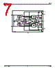
8 / 12 page  MIC2526 Micrel MIC2526 8 February 2000 Functional Description The MIC2526-1 and MIC2526-2 are dual high-side switches with active-high and active-low enable inputs, respectively. Fault conditions turn off or inhibit turn-on of one or more of the output transistors, depending upon the type of fault, and activate the open-drain error flag transistors making them sink current to ground. Input and Output IN (input) is the power supply connection to the logic circuitry and the drain of the output MOSFET. OUTx (output) is the source of its respective MOSFET. In a typical circuit, current flows through the switch from IN to OUT toward the load. If V OUT is greater than VIN when a switch is enabled, current will flow from OUT to IN since the MOSFET is bidirectional when on. The output MOSFET and driver circuitry are also designed to allow the MOSFET source to be externally forced to a higher voltage than the drain (V OUT > VIN) when the output is off. In this situation, the MIC2526 avoids undesirable current flow from OUT to IN. If V IN < 2.5V, UVLO disables both switches. Thermal Shutdown Thermal shutdown shuts off the affected output MOSFETs and signals all fault flags if the die temperature exceeds 135 °C. 10°C of hysteresis prevents the switch from turning on until the die temperature drops to 125 °C. Overtemperature detection functions only when at least one switch is enabled. Current Limit Induced Thermal Shutdown Internal circuitry increases the output MOSFET on-resis- tance until the series combination of the MOSFET on-resis- tance and the load impedance limit current to typically 850mA. The increase in power dissipation, in most cases, will cause the MIC2526 to go into thermal shutdown, disabling affected channels. When this is undesirable, thermal shutdown can be avoided by externally responding to the fault and disabling the current limited channel before the shutdown temperature is reached. The delay between the flag indication of a current limit fault and thermal shutdown will vary with ambient tem- perature, board layout, and load impedance, but is typically several hundred milliseconds. The USB controller must there- fore recognize a fault and disable the appropriate channel within this time. If the fault is not removed or the switch is not disabled within this time, then the device will enter into a thermal oscillation of about 2Hz. This does not cause any damage to the device. Refer to “Functional Characteristics: Thermal Shutdown Response.” Undervoltage Lockout UVLO (undervoltage lockout) prevents the output MOSFET from turning on until V IN exceeds approximately 2.5V. In the undervoltage state, the FLAG will be low. After the switch turns on, if the voltage drops below approximately 2.3V, UVLO shuts off the output MOSFET and signals fault flag. Undervoltage detection functions only when at least one switch is enabled. Current Sensing and Limiting The current-limit threshold is preset internally. The preset level prevents damage to the output MOSFET and external load but allows a minimum current of 0.5A through the output MOSFET of each channel. The current-limit circuit senses a portion of the output FET switch current. The current sense resistor shown in the block diagram is virtual and has no voltage drop. The reaction to an overcurrent condition varies with three scenarios: Switch Enabled into Short Circuit If a switch is powered on or enabled into a heavy load or short- circuit, the switch immediately goes into a constant-current mode, reducing the output voltage. The fault flag goes low until the load is reduced. See the “Functional Characteristics: Short Circuit Response, Enabled into Short Circuit” photo. Short Circuit Applied to Output When a heavy load is applied, a large transient current may flow until the current limit circuitry will respond. Once this occurs, the device limits current to less than the short-circuit current limit specification. See the “Short Circuit Transient Response, Short Applied to Output” graph. Current-Limit Response The MIC2526 current-limit profile exhibits a small foldback effect of approximately 500mA. Once this current-limit thresh- old is exceeded the device enters constant-current mode. This constant current is specified as the short circuit current limit in the “Electrical Characteristics” table. It is important to note that the MIC2526 will deliver load current up to the current-limit threshold which is typically 1.6A. Refer to “Func- tional Characteristics: Current-Limit Response” photo for details. Fault Flag FLG is an N-channel, open-drain MOSFET output. The fault- flag is active (low) for one or more of the following conditions: undervoltage (while 2V < V IN < 2.7), current limit, or thermal shutdown. The flag output MOSFET is capable of sinking a 10mA load to typically 100mV above ground. Multiple FLG pins may be “wire NORed” to a common pull-up resistor. |
|
|
Link URL |
| Does ALLDATASHEET help your business so far? [ DONATE ] |
About Alldatasheet | Advertisement | Contact us | Privacy Policy | Link to Datasheet | Link Exchange | Manufacturer List All Rights Reserved©Alldatasheet.com |
| Russian : Alldatasheetru.com | Korean : Alldatasheet.co.kr | Spanish : Alldatasheet.es | French : Alldatasheet.fr | Italian : Alldatasheetit.com Portuguese : Alldatasheetpt.com | Polish : Alldatasheet.pl | Vietnamese : Alldatasheet.vn Indian : Alldatasheet.in | Mexican : Alldatasheet.com.mx | British : Alldatasheet.co.uk | New Zealand : Alldatasheet.co.nz |
|
Family Site : ic2ic.com |
icmetro.com |
 English ▼
 English
 Chinese
 German
 Japanese
 Russian
 Korean
 Spanish
 French
 Italian
 Portuguese
 Polish
 Vietnamese
 Indian
 Mexican
 British
 New Zealand