|
Electronic Components Datasheet Search |
|
|
Electronic Components Datasheet Search |
|
SA2159 Datasheet(PDF) 6 Page - Silan Microelectronics Joint-stock |
|
|
|||||||||||||||||||||||||||||
SA2159 Datasheet(HTML) 6 Page - Silan Microelectronics Joint-stock |
|
|
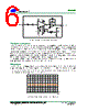
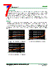
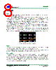
6 / 11 page  SA2159 HANGZHOU SILAN MICROELECTRONICS CO.,LTD Rev: 1.0 2005.04.22 Http: www.silan.com.cn Page 6 of 11 Figure 4. Using Both Control Ports Pin 2 and Pin4 Control port source impedance The control ports (pin 2 through 4) are connected directly to the bases of the logging and /or antilogging transistors. Since the collector currents of transistors are signal-related, the base currents will also be signal- related. If the source impedance of the control voltage is large, the signal-related base currents will cause signal- related voltage to appear at the control ports, which will affect precise logging and antilogging, in turn causing distortion. At high signal levels, even 100 Ω can spoil the good performance of these parts. Due to signal current based on a transistor β of approximately 300(NPN) or 100(PNP), the distortion caused by a specific and non-zero source impedance by determining the base voltage modulation can be estimated. In SA2159 VCA design, the source impedance of pin 2 and pin 3 are zero, while the source impedance of pin 4 is 50 Ω because pin 4 is intended for connection to the symmetry control. DC input signals Any dc currents in the feedback loop of the internal op amp will show up as dc terms in the output signal, and will be modulated by gain commands. The bias current compensation circuit inside the chip offers the input bias current to the input differential amplifier. Ac input coupling is strongly recommended to prevent an input dc current supplied from external application circuit of the VCA. Figure 5. DC offset vs. gain, after symmetry adjustment |
|
|
Link URL |
| Does ALLDATASHEET help your business so far? [ DONATE ] |
About Alldatasheet | Advertisement | Contact us | Privacy Policy | Link to Datasheet | Link Exchange | Manufacturer List All Rights Reserved©Alldatasheet.com |
| Russian : Alldatasheetru.com | Korean : Alldatasheet.co.kr | Spanish : Alldatasheet.es | French : Alldatasheet.fr | Italian : Alldatasheetit.com Portuguese : Alldatasheetpt.com | Polish : Alldatasheet.pl | Vietnamese : Alldatasheet.vn Indian : Alldatasheet.in | Mexican : Alldatasheet.com.mx | British : Alldatasheet.co.uk | New Zealand : Alldatasheet.co.nz |
|
Family Site : ic2ic.com |
icmetro.com |
 English ▼
 English
 Chinese
 German
 Japanese
 Russian
 Korean
 Spanish
 French
 Italian
 Portuguese
 Polish
 Vietnamese
 Indian
 Mexican
 British
 New Zealand