|
Electronic Components Datasheet Search |
|
|
Electronic Components Datasheet Search |
|
ADP5360ACBZ-2-R7 Datasheet(PDF) 23 Page - Analog Devices |
|
|
|||||||||||||||||||||||||||||
ADP5360ACBZ-2-R7 Datasheet(HTML) 23 Page - Analog Devices |
|
|
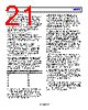
23 / 60 page  Data Sheet ADP5360 Rev. 0 | Page 23 of 60 BATTERY TEMPERATURE Battery Pack Thermistor Input The ADP5360 charger features battery pack temperature sensing that precludes charging when the battery pack temperature is outside of the specified range. The THR pin provides three programmable current sources: 60 μA, 12 μA, and 6 μA. Accordingly, the THR pin supports 10 kΩ, 47 kΩ, and 100 kΩ NTC resistors at 25°C. The THR pin is connected directly to the battery pack thermistor terminal. When the THR function is enabled, the THR node voltage is sensed by the ADC and can be read in the 12-bit registers, THR_V_HIGH and THR_V_LOW. Calculate the external thermistor value (RNTC) by using the following equation: RNTC = (THR_V/60 µA) where: THR_V is the ADC readback from the THR_V_HIGH and THR_V_LOW registers. 60 μA is selected by the THR pin source current. To achieve the battery temperature, the RNTC value must be known. When VVBUS is higher than VVBUS_OK_RISE, the THR function is forced to enable for the charger control requirement. The update rate is 1 second. When VVBUS is lower than VVBUS_OK_RISE, set the EN_THR bit (Address 0x0A) high to enable the THR function. To save quiescent current the THR node voltage update rate slows to 30 seconds. If the battery pack thermistor is not connected directly to the THR pin, a 100 kΩ (tolerance ±20%) dummy resistor must be connected between the THR pin and the AGND1 and AGND2 pins. Leaving the THR pin open results in a false detection of a <0°C battery temperature, and charging disables. The ADP5360 charger monitors the voltage on the THR pin and suspends charging if the voltage is less than 0°C or higher than 60°C. For temperatures greater than 0°C and lower than 60°C, the THR_STATUS[2:0] bits,Address 0x09, are set accordingly. JEITA Li-Ion Battery Temperature Charging Specification The charge of the ADP5360 is compliant with the JEITA Li-Ion battery charging temperature specifications as shown in Table 13. The JEITA function can be enabled via the I2C interface. When the ADP5360 detects a JEITA cool condition, the charging current reduces, as shown in Table 14. When the ADP5360 identifies a hot or cold battery condition, the battery isolation FET turns off. The VSYS pin is linear regulated at VSYS_REG and provides power for the system. Table 13. JEITA Li-Ion Battery Charging Specification Defaults Parameter Symbol Conditions Min Max Unit JEITA Cold Temperature Limits IJEITA_COLD No battery charging occurs. 0 °C JEITACool Temperature Limits IJEITA_COOL Battery charging occurs at approximately 50% or 10% of programmed level. See Table 14 for specific charging current reduction levels. 0 10 °C JEITATypical Temperature Limits IJEITA_TYP Normal battery charging occurs at default and programmed levels. 10 45 °C JEITAWarm Temperature Limits IJEITA_WARM Battery termination voltage (VTRM) is reduced by 100 mV from programmed value. 45 60 °C JEITA Hot Temperature Limits IJEITA_HOT No battery charging occurs. 60 °C Table 14. JEITA Cool Temperature Limit—Reduced Charge Current Levels ICHG[4:0] Value (mA) ICHG JEITAValue (mA) ILIM_JEITA_COOL = 0 ILIM_JEITA_COOL = 1 00000 = 10 10 10 00001 = 20 10 10 00010 = 30 10 10 00011 = 40 20 10 00100 = 50 20 10 00101 = 60 30 10 00110 = 70 30 10 00111 = 80 40 10 01000 = 90 40 10 01001 = 100 50 10 01010 = 110 50 10 01011 = 120 60 10 01100 = 130 60 10 |
|
Link URL |
| Does ALLDATASHEET help your business so far? [ DONATE ] |
About Alldatasheet | Advertisement | Contact us | Privacy Policy | Link to Datasheet | Link Exchange | Manufacturer List All Rights Reserved©Alldatasheet.com |
| Russian : Alldatasheetru.com | Korean : Alldatasheet.co.kr | Spanish : Alldatasheet.es | French : Alldatasheet.fr | Italian : Alldatasheetit.com Portuguese : Alldatasheetpt.com | Polish : Alldatasheet.pl | Vietnamese : Alldatasheet.vn Indian : Alldatasheet.in | Mexican : Alldatasheet.com.mx | British : Alldatasheet.co.uk | New Zealand : Alldatasheet.co.nz |
|
Family Site : ic2ic.com |
icmetro.com |
 English ▼
 English
 Chinese
 German
 Japanese
 Russian
 Korean
 Spanish
 French
 Italian
 Portuguese
 Polish
 Vietnamese
 Indian
 Mexican
 British
 New Zealand