|
Electronic Components Datasheet Search |
|
|
Electronic Components Datasheet Search |
|
CC1100-RTY1 Datasheet(PDF) 31 Page - Texas Instruments |
|
|
|
|||||||||||||||||||||||||||||
CC1100-RTY1 Datasheet(HTML) 31 Page - Texas Instruments |
|
|
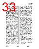
31 / 100 page  CC1100 SWRS038D Page 31 of 92 14.3 Byte Synchronization Byte synchronization is achieved by a continuous sync word search. The sync word is a 16 bit configurable field (can be repeated to get a 32 bit) that is automatically inserted at the start of the packet by the modulator in transmit mode. The demodulator uses this field to find the byte boundaries in the stream of bits. The sync word will also function as a system identifier, since only packets with the correct predefined sync word will be received if the sync word detection in RX is enabled in register MDMCFG2 (see Section 17.1). The sync word detector correlates against the user-configured 16 or 32 bit sync word. The correlation threshold can be set to 15/16, 16/16, or 30/32 bits match. The sync word can be further qualified using the preamble quality indicator mechanism described below and/or a carrier sense condition. The sync word is configured through the SYNC1 and SYNC0 registers. In order to make false detections of sync words less likely, a mechanism called preamble quality indication (PQI) can be used to qualify the sync word. A threshold value for the preamble quality must be exceeded in order for a detected sync word to be accepted. See Section 17.2 on page 37 for more details. 15 Packet Handling Hardware Support The CC1100 has built-in hardware support for packet oriented radio protocols. In transmit mode, the packet handler can be configured to add the following elements to the packet stored in the TX FIFO: • A programmable number of preamble bytes • A two byte synchronization (sync) word. Can be duplicated to give a 4-byte sync word (recommended). It is not possible to only insert preamble or only insert a sync word. • A CRC checksum computed over the data field. • • The recommended setting is 4-byte preamble and 4-byte sync word, except for 500 kBaud data rate where the recommended preamble length is 8 bytes. • • In addition, the following can be implemented on the data field and the optional 2-byte CRC checksum: • • Whitening of the data with a PN9 sequence. • Forward error correction by the use of interleaving and coding of the data (convolutional coding). • In receive mode, the packet handling support will de-construct the data packet by implementing the following (if enabled): • Preamble detection. • Sync word detection. • CRC computation and CRC check. • One byte address check. • Packet length check (length byte checked against a programmable maximum length). • De-whitening • De-interleaving and decoding • Optionally, two status bytes (see Table 21 and Table 22) with RSSI value, Link Quality Indication, and CRC status can be appended in the RX FIFO. • Bit Field Name Description 7:0 RSSI RSSI value Table 21: Received Packet Status Byte 1 (first byte appended after the data) Bit Field Name Description 7 CRC_OK 1: CRC for received data OK (or CRC disabled) 0: CRC error in received data 6:0 LQI Indicating the link quality Table 22: Received Packet Status Byte 2 (second byte appended after the data) • • Note that register fields that control the packet handling features should only be altered when CC1100 is in the IDLE state. 15.1 Data Whitening From a radio perspective, the ideal over the air data are random and DC free. This results in the smoothest power distribution over the occupied bandwidth. This also gives the regulation loops in the receiver uniform operation conditions (no data dependencies). |
|
Link URL |
| Does ALLDATASHEET help your business so far? [ DONATE ] |
About Alldatasheet | Advertisement | Contact us | Privacy Policy | Link to Datasheet | Link Exchange | Manufacturer List All Rights Reserved©Alldatasheet.com |
| Russian : Alldatasheetru.com | Korean : Alldatasheet.co.kr | Spanish : Alldatasheet.es | French : Alldatasheet.fr | Italian : Alldatasheetit.com Portuguese : Alldatasheetpt.com | Polish : Alldatasheet.pl | Vietnamese : Alldatasheet.vn Indian : Alldatasheet.in | Mexican : Alldatasheet.com.mx | British : Alldatasheet.co.uk | New Zealand : Alldatasheet.co.nz |
|
Family Site : ic2ic.com |
icmetro.com |
 English ▼
 English
 Chinese
 German
 Japanese
 Russian
 Korean
 Spanish
 French
 Italian
 Portuguese
 Polish
 Vietnamese
 Indian
 Mexican
 British
 New Zealand