|
Electronic Components Datasheet Search |
|
|
Electronic Components Datasheet Search |
|
CC1100-RTY1 Datasheet(PDF) 43 Page - Texas Instruments |
|
|
|
|||||||||||||||||||||||||||||
CC1100-RTY1 Datasheet(HTML) 43 Page - Texas Instruments |
|
|
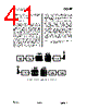
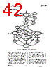
43 / 100 page  CC1100 SWRS038D Page 43 of 92 performance in TX and RX an alternative GDO setting should be selected from the settings found in Table 34 on page 56. 19.1.1 Automatic POR A power-on reset circuit is included in the CC1100. The minimum requirements stated in Table 12 must be followed for the power-on reset to function properly. The internal power- up sequence is completed when CHIP_RDYn goes low. CHIP_RDYn is observed on the SO pin after CSn is pulled low. See Section 10.1 for more details on CHIP_RDYn. When the CC1100 reset is completed the chip will be in the IDLE state and the crystal oscillator will be running. If the chip has had sufficient time for the crystal oscillator to stabilize after the power-on-reset the SO pin will go low immediately after taking CSn low. If CSn is taken low before reset is completed the SO pin will first go high, indicating that the crystal oscillator is not stabilized, before going low as shown in Figure 17. Figure 17: Power-On Reset 19.1.2 Manual Reset The other global reset possibility on CC1100 uses the SRES command strobe. By issuing this strobe, all internal registers and states are set to the default, IDLE state. The manual power-up sequence is as follows (see Figure 18): • Set SCLK = 1 and SI = 0, to avoid potential problems with pin control mode (see Section 11.3 on page 29). • Strobe CSn low / high. • Hold CSn high for at least 40µs relative to pulling CSn low • Pull CSn low and wait for SO to go low (CHIP_RDYn). • Issue the SRES strobe on the SI line. • When SO goes low again, reset is complete and the chip is in the IDLE state. CSn SO XOSC Stable XOSC and voltage regulator switched on SI SRES 40 us Figure 18: Power-On Reset with SRES Note that the above reset procedure is only required just after the power supply is first turned on. If the user wants to reset the CC1100 after this, it is only necessary to issue an SRES command strobe. 19.2 Crystal Control The crystal oscillator (XOSC) is either automatically controlled or always on, if MCSM0.XOSC_FORCE_ON is set. In the automatic mode, the XOSC will be turned off if the SXOFF or SPWD command strobes are issued; the state machine then goes to XOFF or SLEEP respectively. This can only be done from the IDLE state. The XOSC will be turned off when CSn is released (goes high). The XOSC will be automatically turned on again when CSn goes low. The state machine will then go to the IDLE state. The SO pin on the SPI interface must be pulled low before the SPI interface is ready to be used; as described in Section 10.1 on page 26. If the XOSC is forced on, the crystal will always stay on even in the SLEEP state. Crystal oscillator start-up time depends on crystal ESR and load capacitances. The electrical specification for the crystal oscillator can be found in Section 4.4 on page 14. 19.3 Voltage Regulator Control The voltage regulator to the digital core is controlled by the radio controller. When the chip enters the SLEEP state, which is the state with the lowest current consumption, the voltage regulator is disabled. This occurs after CSn is released when a SPWD command strobe has been sent on the SPI interface. The chip is now in the SLEEP state. Setting CSn |
|
Link URL |
| Does ALLDATASHEET help your business so far? [ DONATE ] |
About Alldatasheet | Advertisement | Contact us | Privacy Policy | Link to Datasheet | Link Exchange | Manufacturer List All Rights Reserved©Alldatasheet.com |
| Russian : Alldatasheetru.com | Korean : Alldatasheet.co.kr | Spanish : Alldatasheet.es | French : Alldatasheet.fr | Italian : Alldatasheetit.com Portuguese : Alldatasheetpt.com | Polish : Alldatasheet.pl | Vietnamese : Alldatasheet.vn Indian : Alldatasheet.in | Mexican : Alldatasheet.com.mx | British : Alldatasheet.co.uk | New Zealand : Alldatasheet.co.nz |
|
Family Site : ic2ic.com |
icmetro.com |
 English ▼
 English
 Chinese
 German
 Japanese
 Russian
 Korean
 Spanish
 French
 Italian
 Portuguese
 Polish
 Vietnamese
 Indian
 Mexican
 British
 New Zealand