|
Electronic Components Datasheet Search |
|
|
Electronic Components Datasheet Search |
|
CC1100-RTY1 Datasheet(PDF) 34 Page - Texas Instruments |
|
|
|
|||||||||||||||||||||||||||||
CC1100-RTY1 Datasheet(HTML) 34 Page - Texas Instruments |
|
|
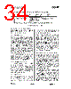
34 / 100 page  CC1100 SWRS038D Page 34 of 92 0,1,..........,88,....................255,0,........,88,..................,255,0,........,88,..................,255,0,....................... Internal byte counter in packet handler counts from 0 to 255 and then starts at 0 again Length field transmitted and received. Rx and Tx PKTLEN value set to mod(600,256) = 88 Infinite packet length enabled Fixed packet length enabled when less than 256 bytes remains of packet 600 bytes transmitted and received Figure 12: Packet Length > 255 15.3 Packet Filtering in Receive Mode CC1100 supports three different types of packet-filtering; address filtering, maximum length filtering, and CRC filtering. 15.3.1 Address Filtering Setting PKTCTRL1.ADR_CHK to any other value than zero enables the packet address filter. The packet handler engine will compare the destination address byte in the packet with the programmed node address in the ADDR register and the 0x00 broadcast address when PKTCTRL1.ADR_CHK=10 or both 0x00 and 0xFF broadcast addresses when PKTCTRL1.ADR_CHK=11 . If the received address matches a valid address, the packet is received and written into the RX FIFO. If the address match fails, the packet is discarded and receive mode restarted (regardless of the MCSM1.RXOFF_MODE setting). If the received address matches a valid address when using infinite packet length mode and address filtering is enabled, 0xFF will be written into the RX FIFO followed by the address byte and then the payload data. 15.3.2 Maximum Length Filtering In variable packet length mode, PKTCTRL0.LENGTH_CONFIG=1 , the PKTLEN.PACKET_LENGTH register value is used to set the maximum allowed packet length. If the received length byte has a larger value than this, the packet is discarded and receive mode restarted (regardless of the MCSM1.RXOFF_MODE setting). 15.3.3 CRC Filtering The filtering of a packet when CRC check fails is enabled by setting PKTCTRL1.CRC_AUTOFLUSH=1 . The CRC auto flush function will flush the entire RX FIFO if the CRC check fails. After auto flushing the RX FIFO, the next state depends on the MCSM1.RXOFF_MODE setting. When using the auto flush function, the maximum packet length is 63 bytes in variable packet length mode and 64 bytes in fixed packet length mode. Note that the maximum allowed packet length is reduced by two bytes when PKTCTRL1.APPEND_STATUS is enabled, to make room in the RX FIFO for the two status bytes appended at the end of the packet. Since the entire RX FIFO is flushed when the CRC check fails, the previously received packet must be read out of the FIFO before receiving the current packet. The MCU must not read from the current packet until the CRC has been checked as OK. 15.4 Packet Handling in Transmit Mode The payload that is to be transmitted must be written into the TX FIFO. The first byte written must be the length byte when variable packet length is enabled. The length byte has a value equal to the payload of the packet (including the optional address byte). If address recognition is enabled on the receiver, the second byte written to the TX FIFO must be the address byte. If fixed packet length is enabled, then the first byte written to the TX FIFO should be the address (if the receiver uses address recognition). The modulator will first send the programmed number of preamble bytes. If data is available in the TX FIFO, the modulator will send the two-byte (optionally 4-byte) sync word and then the payload in the TX FIFO. If CRC is enabled, the checksum is calculated over all the data pulled from the TX FIFO and the result is sent as two extra bytes following the payload data. If the TX FIFO runs empty before the complete packet has been |
|
Link URL |
| Does ALLDATASHEET help your business so far? [ DONATE ] |
About Alldatasheet | Advertisement | Contact us | Privacy Policy | Link to Datasheet | Link Exchange | Manufacturer List All Rights Reserved©Alldatasheet.com |
| Russian : Alldatasheetru.com | Korean : Alldatasheet.co.kr | Spanish : Alldatasheet.es | French : Alldatasheet.fr | Italian : Alldatasheetit.com Portuguese : Alldatasheetpt.com | Polish : Alldatasheet.pl | Vietnamese : Alldatasheet.vn Indian : Alldatasheet.in | Mexican : Alldatasheet.com.mx | British : Alldatasheet.co.uk | New Zealand : Alldatasheet.co.nz |
|
Family Site : ic2ic.com |
icmetro.com |
 English ▼
 English
 Chinese
 German
 Japanese
 Russian
 Korean
 Spanish
 French
 Italian
 Portuguese
 Polish
 Vietnamese
 Indian
 Mexican
 British
 New Zealand